5-52 ADS TRITON+ Manual
Note: This value will be necessary when configuring the
monitor using the Qstart
XML
software.
12. Run the sensor cables from the sensor location in the pipe to
the monitor location in the manhole according to the
instructions in Securing the Sensor Cables in the Pipe and
Manhole on page 5-80.
Note: If the pipe is large and the sensor cable cannot
reach the pipe crown, attach the sensor cables to 0.5-inch
(12-mm) PVC tubing and anchor the tubing to the wall.
This will help prevent sensor damage during heavy flow.
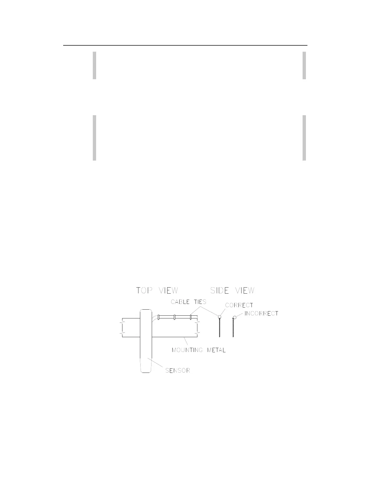
Securing the Cables to the Band
Securing the underwater sensor cable to the band helps prevent
debris from collecting between the cable and the band or catching
on the loose cable. It also prevents the loose cables from disrupting
the flow.
Secure the cable in the following way:
1. Starting at the appropriate sensor location, begin securing the
sensor cable with 4-inch
(2-mm x 100-mm) cable ties through
the pre-drilled holes along the downstream (trailing) edge of
the band up the side of the band. Run the cable up the right
side of the band (on the downstream edge of the band).
Sensor cabling
2. Continue securing the cables until reaching the ParaDeph,
ParaFlow, Surface Combo, or Ultrasonic Depth Sensor, or top
of the pipe.