Communication 3-13
the (mastic covered version) antenna. The corbel hole should
be at the end closest to the manhole cover.
4. Drill a hole in the end of the cut closest to the manhole cover
through the corbel, and into the manhole using the ½-inch (13-
mm) by 36-inch (914-mm) hammer drill bit. This will serve as
the channel for the antenna cable extending from the antenna to
the monitor in the manhole. Be careful to avoid any cables in
the manhole, and restart the hole slightly to the right or left if
mesh is encountered or resistance occurs.
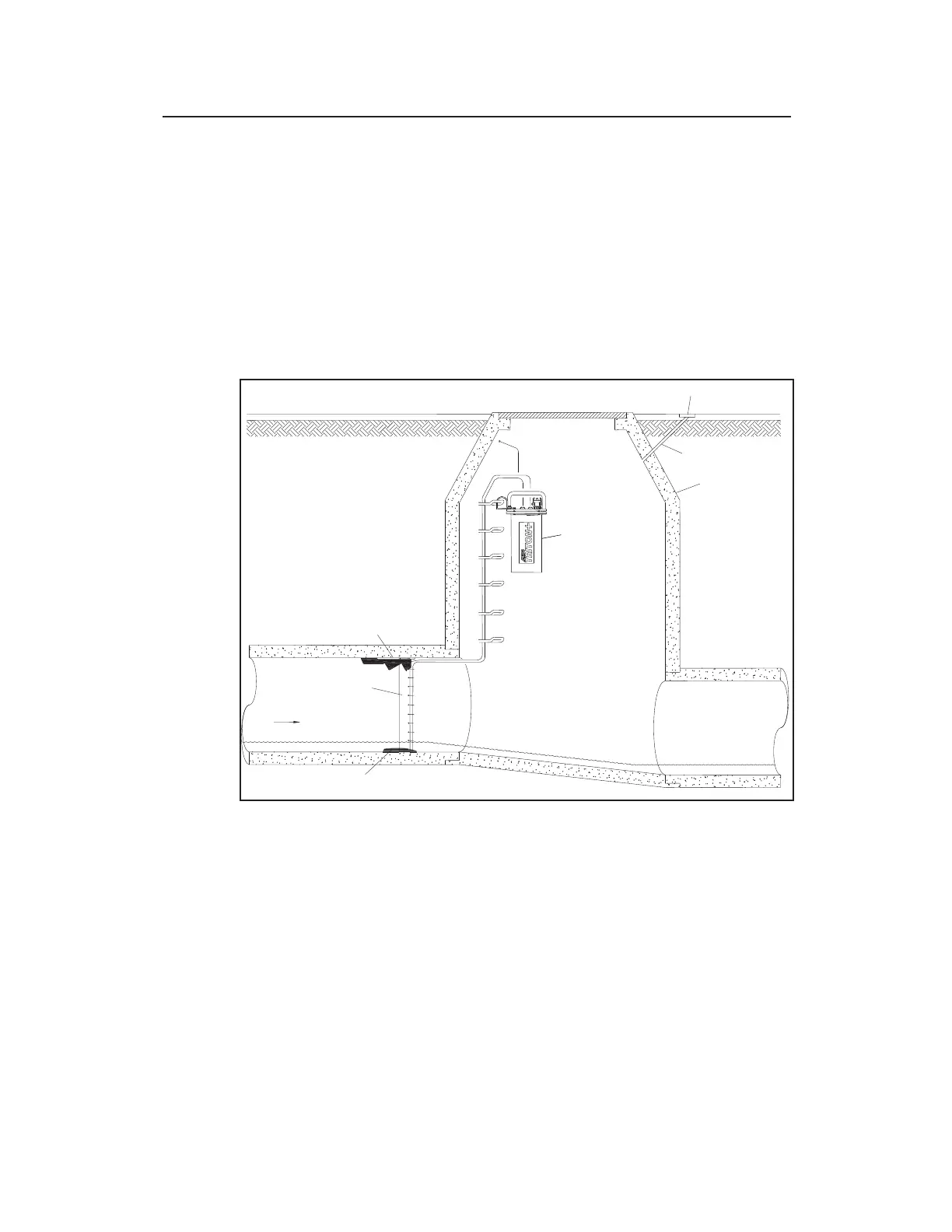
Hole Running from Antenna Installation Location to Manhole
5. Thoroughly clean out the hole for the antenna of all debris
using a shop vacuum with a brush.
6. If the protective cap is not present on the connector at the end
of the antenna cable, clean the connector and tape it up with
rubber stretch tape for protection against damage and debris
while it is being fed through the channel.
7. Feed all of the antenna cable into the hole, through the channel,
and into the manhole. Smooth any rough edges where the