4-Channel Digital Video Recorder
5
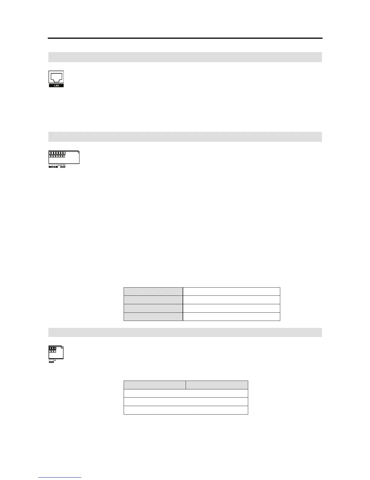
Network Port
The DVR can be networked using the 10/100Mb Ethernet connector. Connect a
Cat5 cable with an RJ-45 jack to the DVR connector. The DVR can be networked
with a computer for remote monitoring, searching, configuration and software
upgrades. See Chapter 3 Configuration for configuring the Ethernet connections.
CAUTION: The network connector is not designed to be connected directly with cable
or wire intended for outdoor use
.
Alarm Input/Output
NOTE: To make connections on the Alarm Connector Strip, press and hold
the button and insert the wire in the hole below the button. After releasing
the button, tug gently on the wire to make certain it is connected. To
disconnect a wire, press and hold the button above the wire and pull out
the wire.
Alarm In 1 to 4 (Alarm-In): You can use external devices to signal the DVR to react to events.
Mechanical or electrical switches can be wired to the AI (Alarm-In) and GND (Ground) connectors.
The threshold voltage for NC (Normally Closed) is above 4.3V and for NO (Normally Open) is
below 0.3V, and it should be stable at least 0.5 seconds to be detected. See Chapter 3 Configuration
for configuring alarm input.
GND (Ground): Connect the ground side of the Alarm input and/or alarm output to the GND
connector.
NOTE: All the connectors marked GND are common.
NO (Normally Open): Connect the device to the COM and NO (Normally Open) connector.
NO is a relay output which sinks 1A@30VDC.
Connector Pin Outs:
Alarm In (1 to 4)
Alarm Inputs 1 to 4
GND
Chassis Ground
COM
Common
NO
Alarm Out (Normally Open)
RS485 Port
The RS485 connector can be used to control PTZ (pan, tilt, zoom) cameras. Connect
RX+/TX+ and RX-/ TX- of the control system to the + and – (respectively) of the DVR.
See Chapter 3 Configuration and the PTZ camera’s manual for configuring the
RS485 connection.
Connector Pin Outs:
Master Unit Slave Unit
+ To TX+/RX+
– To TX-/RX-
GND To GND
 Loading...