Advent Communications
209298 - DVE5000 Technical Operation Handbook - CL140042 Page 25 of 110
5. OPERATION GUIDE - EXCITER
5.1. AC POWER CONNECTION
Connect the unit to AC power source at the IEC inlet in the range 90 – 264V.
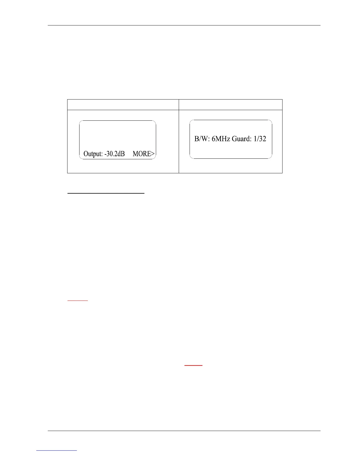
After a few seconds the Advent logo will be displayed followed by the main menu –
Example: L-band DVBS mode Example: 70MHz DVB-T mode
- Exciter Status - SD DVBS
Freq: 14487.000MHz
Rate: 27.5000Msym
Mod: QPSK 1/2
- Exciter Status - SD DVB-T
Freq: 70.000MHz
Mod: 64QAM 7/8
Output: -5.2dB
EXTERNAL CONNECTIONS
Ensure TX key is set to ‘off’ while connecting up signal sources.
Connect composite video PAL/NTSC source to connector labelled ‘CVBS’
(Options) Connect serial digital PAL/NTSC SD / HD source to connector labelled ‘(HD)SDI’.
Connect analogue (or digital option) audio to the rear panel 15 way ‘D’ male connector.
An interface cable (spares part number A41-207359) that adapts this to 4-x XLR female
connector is supplied with the exciter.
With AES /EBU option, the “right channel” XLR becomes the digital input.
If an external ASI stream is to be multiplexed in with the local encoder in the exciter, connect
the external source to BNC labelled ‘ASI IN’.
Caution should be observed as 17V DC may be present on the L-Band output connector.
From the main menu screen shown above, by using the up / down arrow keys to select
parameter required to be changed, press ENTER to confirm or ESCAPE to cancel selection.
Note: output level can be continually adjusted without pressing ENTER key between value
changes, press ENTER or ESCAPE to exit level adjustment.
Output level is shown in dB’s relative to maximum level as defined in the product specification.
NOTE
Before changing parameters that alter signal bandwidth Tx carrier must be OFF.
A warning will be displayed if operator attempts to change a parameter that
requires the carrier to be off.