Advent Communications
209298 - DVE5000 Technical Operation Handbook - CL140042 Page 56 of 110
7. OPERATION PROCEDURE - HPA CONTROL
7.1. INTRODUCTION
The DVE5000 integrates a serial controller for up to two amplifiers, with protocol conversion for
a wide range of HPA / SSPA types.
The control may be via direct RS485 connection at the rear panel D-Type or modulated onto the
L-Band RF output.
The modulated signal can be decoded by AUC5000, Exos and AUC5814 block up-converter
products from Advent.
The HPA control would be connected to the block up-converter in this configuration;
a single L-band cable is the only required connection between the DVE and the HPA
(via the up-converter).
DVE5000 HD-SD EXCITER
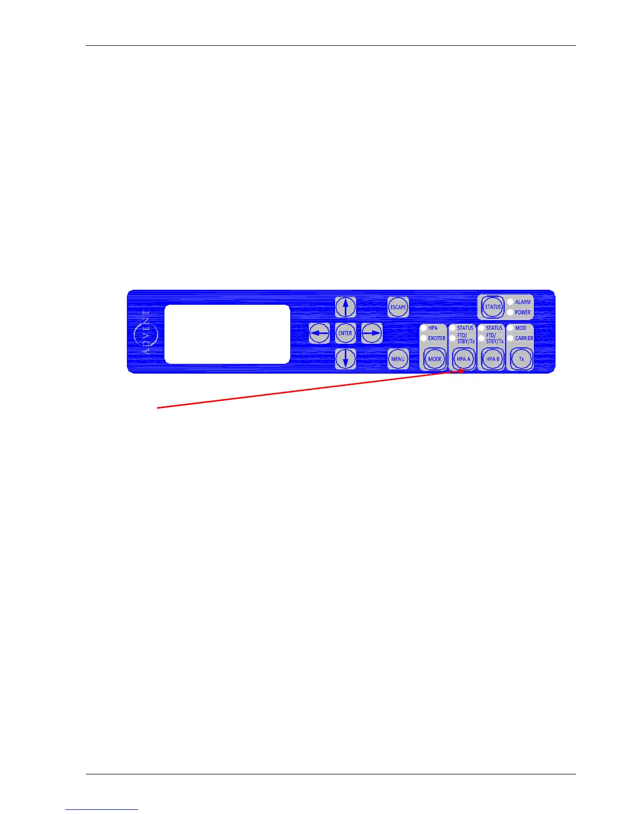
‘Hot Keys’ are provided on the front panel to directly control the operation of the
amplifier between “transmit” and “standby” functions.
Note: SSPA’s do not have “standby” – ‘off’ state is the equivalent.
Led’s are provided for displaying the status of the amplifier(s) at a glance -
STATUS (hpa) - when illuminated green indicates power is applied to the HPA and is
functioning. If illuminated red, this indicates a fault with the HPA.
FTD / STBY / Tx- when flashing amber, HPA is in filament time delay (FTD) going into ‘standby’
when warmed up. If flashing green, HPA is in filament time delay going into ‘transmit’ when
warmed up.
Note: FTD is only applicable to TWTA based amplifiers.