A
4
B
1
C
2
3
11
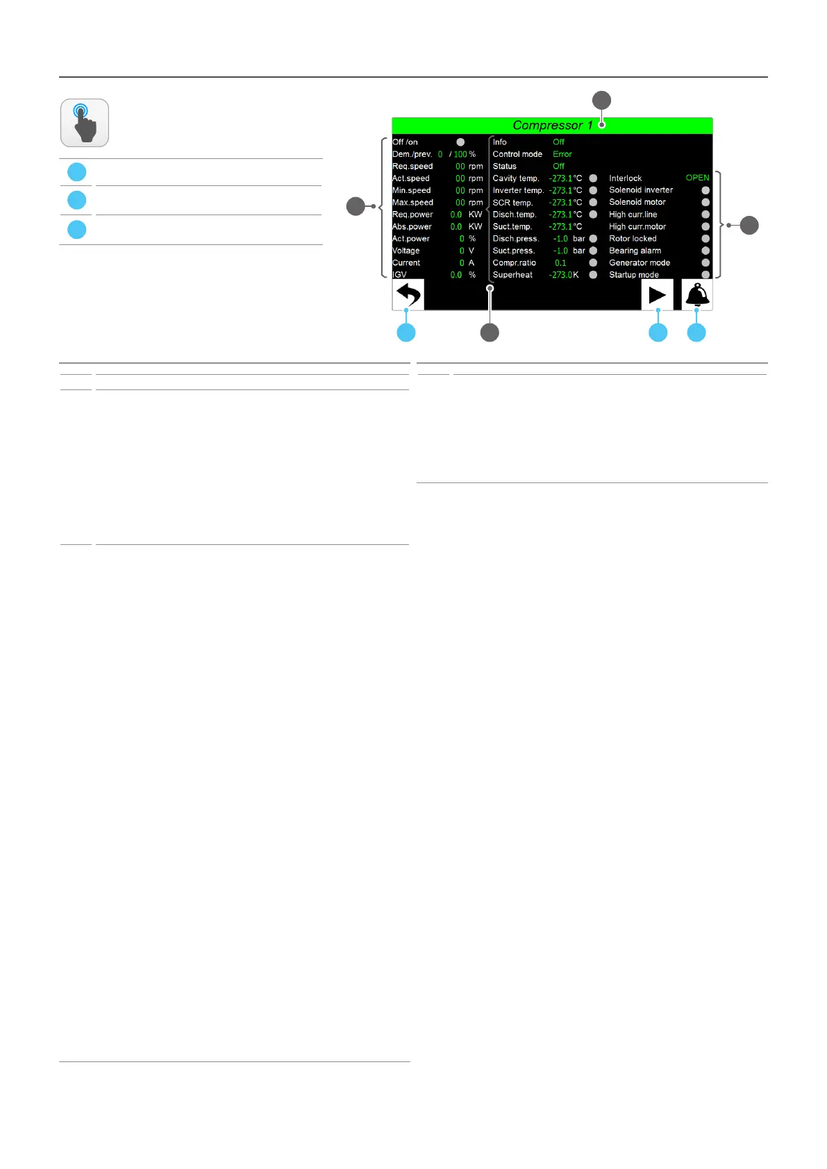
Main monitor - COMPRESSORS page
Index Meaning
1 Indicates which compressor the page data refers to
2
They indicate the current values of the following parameters:
O/on = current status of the compressor (green = On; grey = O );
Req./MaxReq. = power level required by the compressor;
Sp.Req. = target speed which the compressor aims at to achieve the request;
Cur.sp. = current compressor speed;
Min.Sp. = minimum speed value calculated by the compressor per work area;
Max.sp. = maximum speed value calculated by the compressor per work area;
Pow.req. = power value required by the compressor;
Pow.Aabs. = current power absorbed by the compressor;
Cur.pow. = percentage of power currently supplied;
Voltage = voltage of the compressor;
Current = current absorbed by the compressor;
IGV = opening percentage of the IGV valve;
3
They indicate the current values of the following parameters:
Info = indicates the current status of the compressor, this can be:
• O: compressor o;
• On: compressor on;
• Repositioning: compressor o repositioning of the IGV valve in progress;
• Al.Turbocor: compressor in alarm;
• Lim.High TGP: Limit for pressing gas temperature;
• O stable demand: preliminary stage for switching on the new compressor,
the active compressors are required to stabilise at a set speed;
• O write speed: calculation of the target speed for the new compressor at
start-up, checking the current speeds of the active compressors;
• On start compressor: compressor ready for start-up;
• On stag. valve open: staging valve open;
• On closing stag. valve: staging valve closed;
• O time between startup: compressor o for minimum switch-o time;
Mode control = indicates the control mode; this mode can be:
• Error: the compressor signals an error condition;
• Calibration mode: compressor in calibration stage (support only);
• Manual mode: compressor active in manual mode (support only);
• Analog mode: not used;
• Modabus mode: compressor active via command of the pCO board;
• Chiller mode: not used;
Status = indicates the current status of the compressor, it can be:
• o: compressor o;
• Locked out state: situation after an alarm has ceased;
• System Resetting: the compressor is in reset stage;
• Ramping Up: the compressor is in start-up stage;
• Partially Closed Vane: the compressor is closing the IGV valve;
• Normal Operation State: the compressor is operating normally;
• Maximum Flow State: the compressor is operating at full speed;
• Minimum IGV% reached: minimum opening of the IGV valve;
• Interlock Open: the compressor is waiting for consent from the pCO board;
• Fault is Active: the compressor is stopped for alarm;
• Inverter temp. High: high temperature of the internal inverter;
• Ready for demand: the compressor is ready;
(1)
Temp. cavity = indicates the current cavity temperature;
(1)
Temp. inverter = indicates the current temperature of the internal inverter;
(1)
Temp.SCR = indicates the current temperature of the SCR;
(1)
Temp.mand. = indicates the current temperature of the pressing line;
Int.temp. = indicates the current intake temperature;
(1)
Press.mand. = indicates the current pressure of the pressing line;
(1)
Int.pres. = indicates the current intake pressure;
(1)
Compr.rat. = indicates the current value of the compression ratio;
(1)
Superheat = indicates the overheating value;
ACTIONS
AVAILABLE:
A
Return to main monitor
B
Open the Alarms page (if an alarm is currently
present on the system, the icon will ash)
C
Enables to access the page of the next compressor
(if present)
Index Meaning
4
They indicate the current values of the following parameters:
(2)
Interlock = current status of consent to compressor operation;
(2)
Inverter solenoid = current status of the inverter solenoid;
(1)
Line high curr. = current status of the compressor power supply;
(3)
Motor high curr. = motor overcurrent control;
(3)
Rotor blocked = rotor lock control;
(3)
Bearing alarm = bearing alarm control;
(3)
Generator mode = inertial rotation control after stop;
(3)
Start mode = compressor start-up procedures control;
(1)
these signals may have one of the following states:
• grey = standard size;
• yellow = size in pre-alarm;
• red = size in alarm;
(2)
these signs may have one of the following states:
• green = load energised;
• grey = load in standby;
(3)
these signs may have one of the following states:
• grey = standard size;
• yellow = non standard size;