A
D
6
B
E
F
G
C
3 4 5
21
8
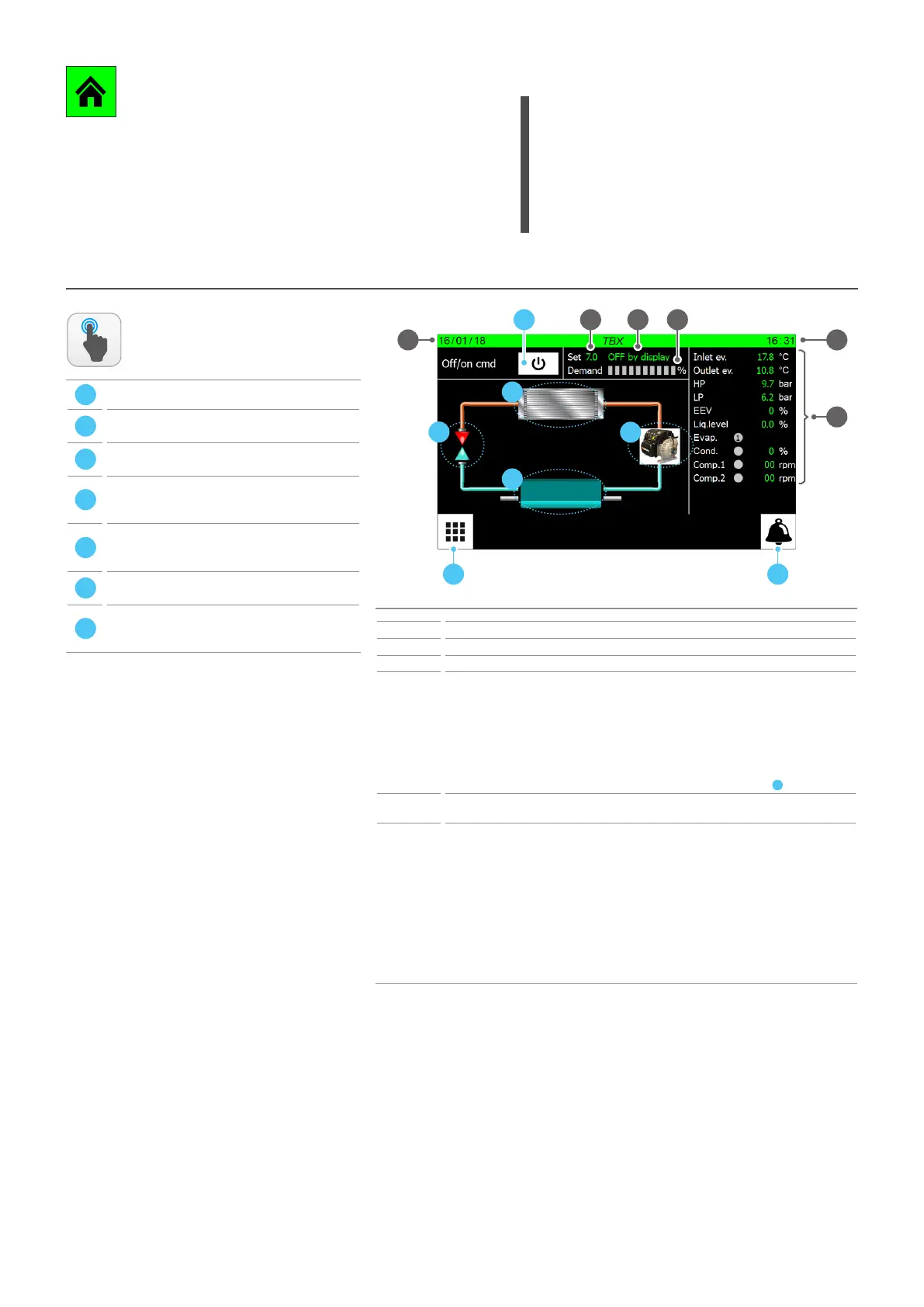
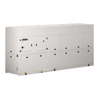
MAIN MONITOR
This page contains general informaon on the current status and operaon
of the unit. Moreover, by pressing the graphical elements that represent
the components of the cooling circuit, it is possible to enter specic sub-
windows where to view the data relang to the selected component;
Main monitor - TBX
Index Meaning
1 Indicates today’s date set on the system
2 Indicates the current date set on the system
3 Indicates the setpoint value currently set
4
Indicates the current status of the unit. This status can be:
WAIT = Unit waiting for control board start (5 seconds);
ON = Unit active;
OFF from alarm = Unit stopped due to alarm;
Board restart = Unit waiting for start procedure (20 seconds);
OFF from BMS = Unit turned o via command incoming from BMS;
OFF from time = Unit turned o from time setting;
OFF from ID = Unit turned o via digital input (ID1);
OFF from Dispaly = Unit turned o from pressing the key on the touch display (
C
);
5
Indicates the current power value required by the thermostat. The power percentage required is
represented by the green colour of the bands (each band indicates a 10% of power)
6
They indicate the current values of the following parameters:
Sv.wat.inl. = Evaporator water inlet temperature;
Sv.wat.out. = Evaporator water outlet temperature;
AP = Value read by the high pressure transducer;
BP = Value read by the low pressure transducer;
EVV = Current opening value (percentage) of the electronic valve;
Liq. level = level of liquid inside the attached heat exchanger;
Evap. = Indicates the status of the pump on the evaporator (green = On; grey = O);
Cond. = Indicates the fan status (green = On; grey = O ), also indicates the fan speed as a
percentage;
Comp.1 = Value of revs for compressor 1;
Comp.2 = Value of revs for compressor 2;
ATTENTION: some pages (or items within the same pages) of
this menu may not be visible as they are specic for certain
models or types of unit (depending on the conguraon,
some components may not be available), however, this
manual will list all possible pages. For further informaon
on the components present in the unit, refer to the technical
manual.
ACTIONS
AVAILABLE:
A
Open the menu selecting page
B
Open the Alarms page (if an alarm is currently
present on the system, the icon will ash)
C
Enables to turn the unit on or o (it turns on if the
background is green, o if it is white)
D
Enables to access the "COMPRESSORS" page (for
further information refer to the later dedicated
section)
E
Enables to access the "ELECTRONIC VALVE" page
(this page is not available on some units. For further
information refer to the later dedicated section)
F
Enables to access the "CONDENSER" page (for further
information refer to the later dedicated section)
G
Enables to access the "EVAPORATOR" page (for
further information refer to the later dedicated
section)