4349B
T
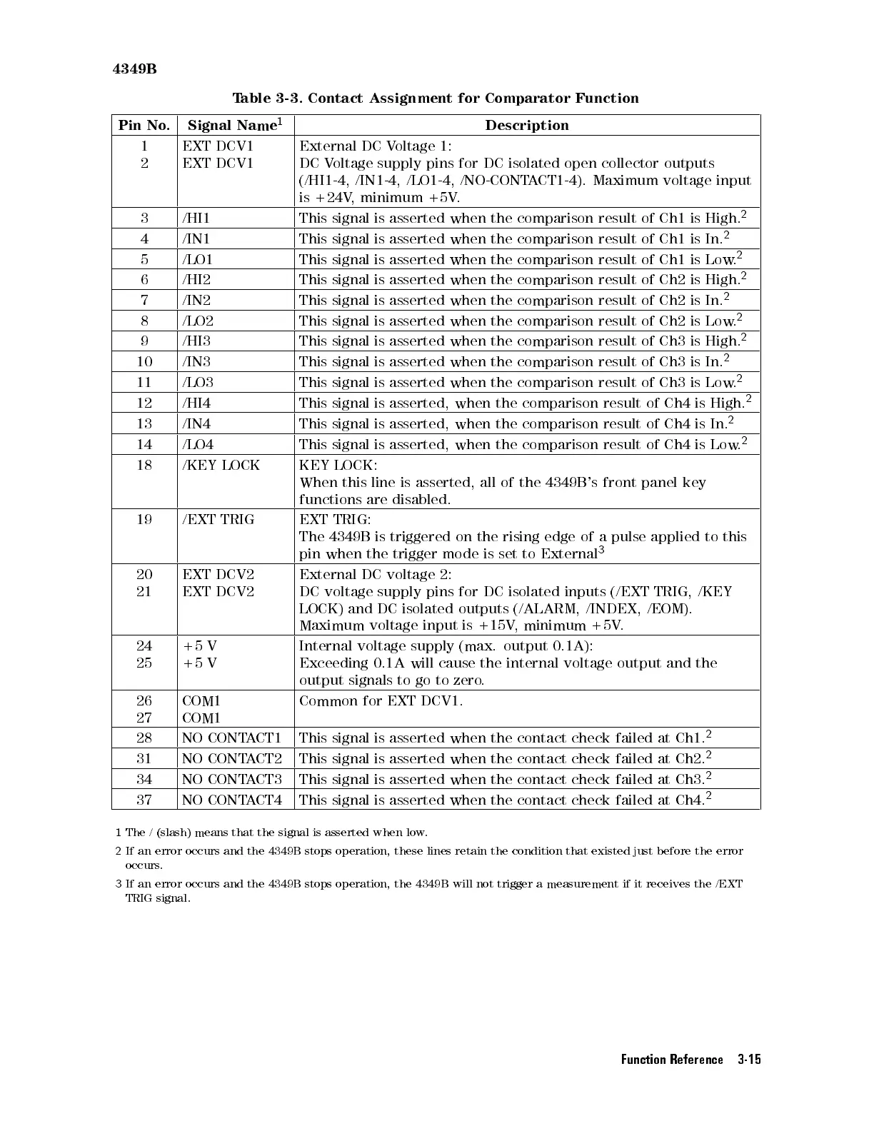
able 3-3.
Contact Assignment
for
Comparator
Function
Pin No
.
Signal Name
1
Description
1
2
EXT
DCV1
EXT
DCV1
External
DC
V
oltage 1:
DC
V
oltage
supply pins
for DC
isolated open
collector outputs
(/HI1-4,
/IN1-4, /LO1-4,
/NO-CONTA
CT1-4). Maximum
voltage input
is
+24V
,
minimum +5V
.
3 /HI1 This
signal is
asserted when
the
comparison
result
of
Ch1
is
High.
2
4 /IN1 This
signal
is
asserted
when
the
comparison
result
of
Ch1
is
In.
2
5 /LO1 This
signal
is asserted
when the
comparison result
of Ch1
is
Low
.
2
6 /HI2 This
signal
is
asserted
when
the
comparison
result
of
Ch2
is
High.
2
7 /IN2 This
signal
is
asserted
when
the
comparison
result of
Ch2 is
In.
2
8 /LO2 This
signal is
asserted when
the
comparison
result
of
Ch2
is
Low
.
2
9 /HI3 This
signal
is
asserted
when
the
comparison
result
of
Ch3
is High.
2
10 /IN3 This signal
is asserted
when the
comparison
result
of
Ch3
is
In.
2
11 /LO3 This
signal
is
asserted
when
the
comparison
result
of
Ch3
is
Low
.
2
12 /HI4 This
signal
is
asserted,
when
the
comparison
result
of
Ch4
is
High.
2
13 /IN4 This
signal
is
asserted,
when
the
comparison
result of
Ch4
is
In.
2
14 /LO4 This
signal
is
asserted,
when the
comparison result
of Ch4
is
Low
.
2
18 /KEY
LOCK
KEY
LOCK:
When
this
line
is
asserted,
all
of
the
4349B
's
front
panel key
functions
are
disabled.
19 /EXT
TRIG
EXT
TRIG:
The
4349B
is triggered
on
the
rising
edge
of
a
pulse
applied
to
this
pin
when
the
trigger mode
is
set
to
External
3
20
21
EXT
DCV2
EXT
DCV2
External
DC
voltage
2:
DC
voltage
supply
pins
for
DC
isolated
inputs
(/EXT
TRIG, /KEY
LOCK)
and
DC
isolated
outputs
(/ALARM,
/INDEX,
/EOM).
Maximum
voltage input
is +15V
,
minimum
+5V
.
24
25
+5
V
+5
V
Internal
voltage
supply
(max.
output
0.1A):
Exceeding
0.1A
will
cause
the
internal
voltage
output
and
the
output
signals
to
go
to
zero
.
26
27
COM1
COM1
Common
for
EXT
DCV1.
28 NO
CONT
A
CT1
This
signal
is
asserted
when
the
contact
check
failed at
Ch1.
2
31 NO
CONT
A
CT2
This
signal
is
asserted
when
the
contact
check
failed
at
Ch2.
2
34 NO CONT
ACT3
This signal is asserted when
the contact check failed at Ch3.
2
37 NO CONT
ACT4
This signal is asserted when the contact check failed at Ch4.
2
1
The / (slash) means that
the signal is asserted when low
.
2
If an error occurs and the 4349B stops operation, these lines retain the condition that existed just before the
error
occurs.
3
If an error occurs and the 4349B
stops operation, the 4349B will not trigger a measurement if it receives the /EXT
TRIG signal.
Function Reference 3-15
 Loading...


