Chapter 5: Troubleshooting
Power Supply Trouble Isolation
5–12
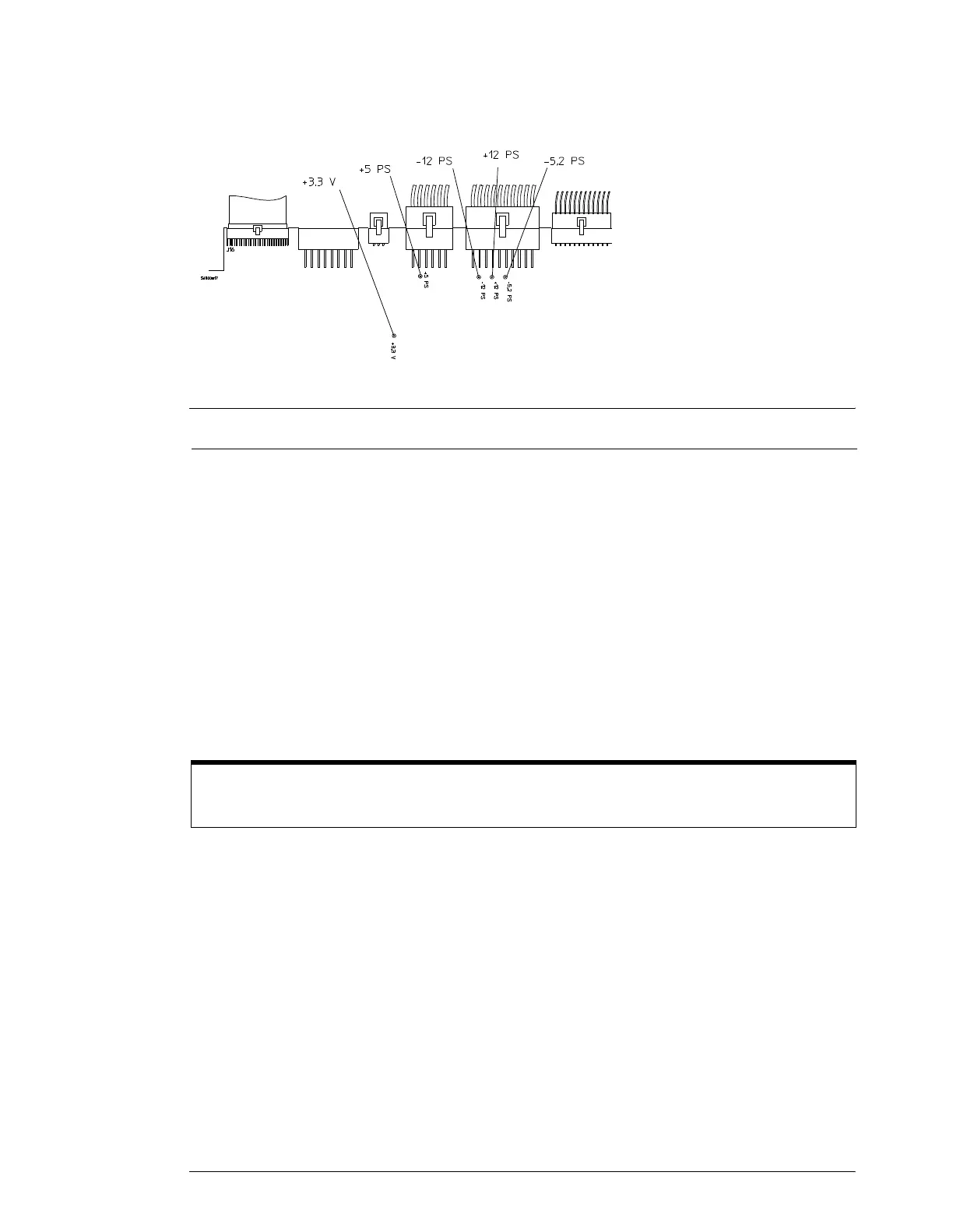
Figure 5-5
P
ower Supply Voltage Test Locations (A13)
Table 5-1
Power Supply Voltage Limits
B
Turn off the power and measure the power supply resistances to ground to check for
shorted supply lines.
You can probe the test points on A13, shown in Figure 5-5, for this resistance check.
C
Replace any shorted assembly.
You can locate the shorted assembly by disconnecting assemblies from the power supply, one at
a time.
4 Override the Remote Inhibit signal.
Power up the by unit removing the W2 control cable from the fan controller board.
E Replace the power supply.
1 If the +15 V bias is correct, but the oscilloscope will not power up with a 196-220Ω
resistor, replace the power supply. Chapter 6 explains how to remove and replace the
power supply.
2 Re-assemble the oscilloscope and apply power.
F Check for the oscilloscope display onscreen.
1 You should see the oscilloscope display (see figure 5-2). If not, see the No Display Trouble
Isolation Flowchart.
2 If you see the display, return to the Primary Trouble Isolation Flowchart.
Supply Voltage Specification Limits
+5.1 V ± 0.1 V +5.0 V to +5.2 V
-5.2 V ± 0.1 V -5.1 V to -5.3 V
+12.2 V ± 0.3 V +11.9 V to +12.5 V
-12.2 V ± 0.3 V -11.9 V to -12.5 V
+3.3 V ± 0.1 V +3.2 V to + 3.4 V
Reconnect Assemblies and Cables
Reconnect all assemblies after testing. The oscilloscope must have all cables connected for correct power
up.
 Loading...


