Chapter 2 163
Making Measurements
Example 13: Making Pulsed RF Measurements
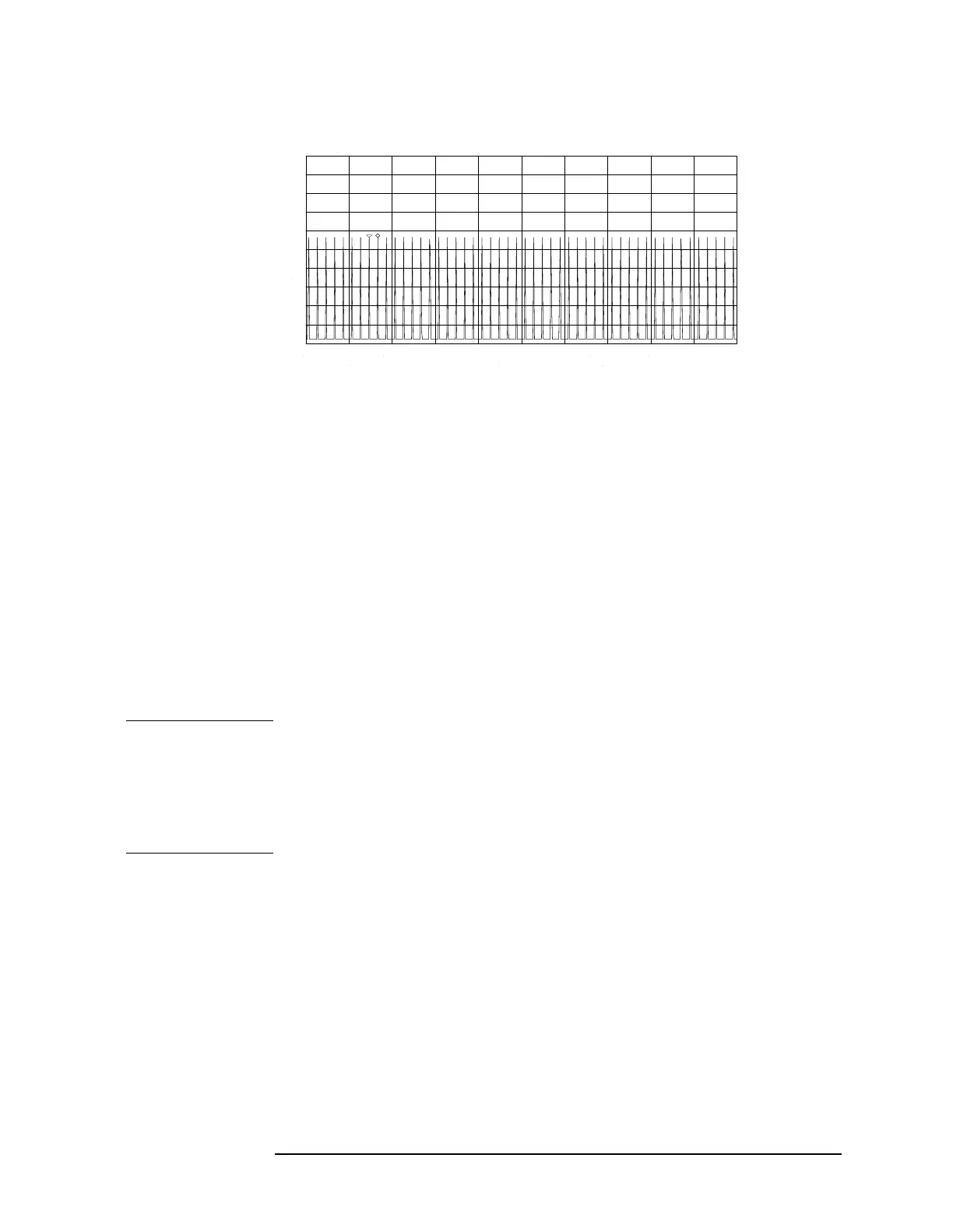
Figure 2-88 Measuring Pulse Repetition Frequency
Peak Pulse Power and Desensitization
Now that you know the main lobe amplitude, the pulse width, and can
easily note the spectrum analyzer resolution bandwidth, the peak pulse
power can be derived from a relatively simple equation:
NOTE While measuring the main lobe amplitude, change the spectrum
analyzer attenuation and check that the main lobe amplitude does not
change. If it changes by more than 1 dB, the analyzer is in compression
and the RF attenuation must be increased. For carrier frequencies
above 2.75 GHz, be sure to peak the preselector to measure the main
lobe amplitude accurately.
The difference between the peak pulse power and the main lobe
amplitude is called pulse desensitization. The term "pulse
desensitization" can be somewhat misleading, because pulsed signals
do not reduce spectrum analyzer sensitivity. Rather, apparent
desensitization occurs because the power of a pulsed continuous wave
(CW) carrier is distributed over a number of spectral components (that
is, the carrier and sidebands). As a result, each spectral component
contains only a fraction of the total power. For a complete discussion of
pulse desensitization, refer to Application Note 150-2 (literature
number 5952-1039) or Appendix A of Application Note 330-1 (literature
number 5954-2705).
Peak Pulse Power Mainlobe Amplitude()20log T
eff
()BW
i
()–=
where T
eff
= pulse width, in seconds
BW
i
= impulse bandwidth, in Hertz
BW
i
= 1.5 × resolution bandwidth used to measure pulse
width.