28 Chapter2
Setting Up the EDGE (with GSM) Mode
EDGE (with GSM) Measurement Key Flow
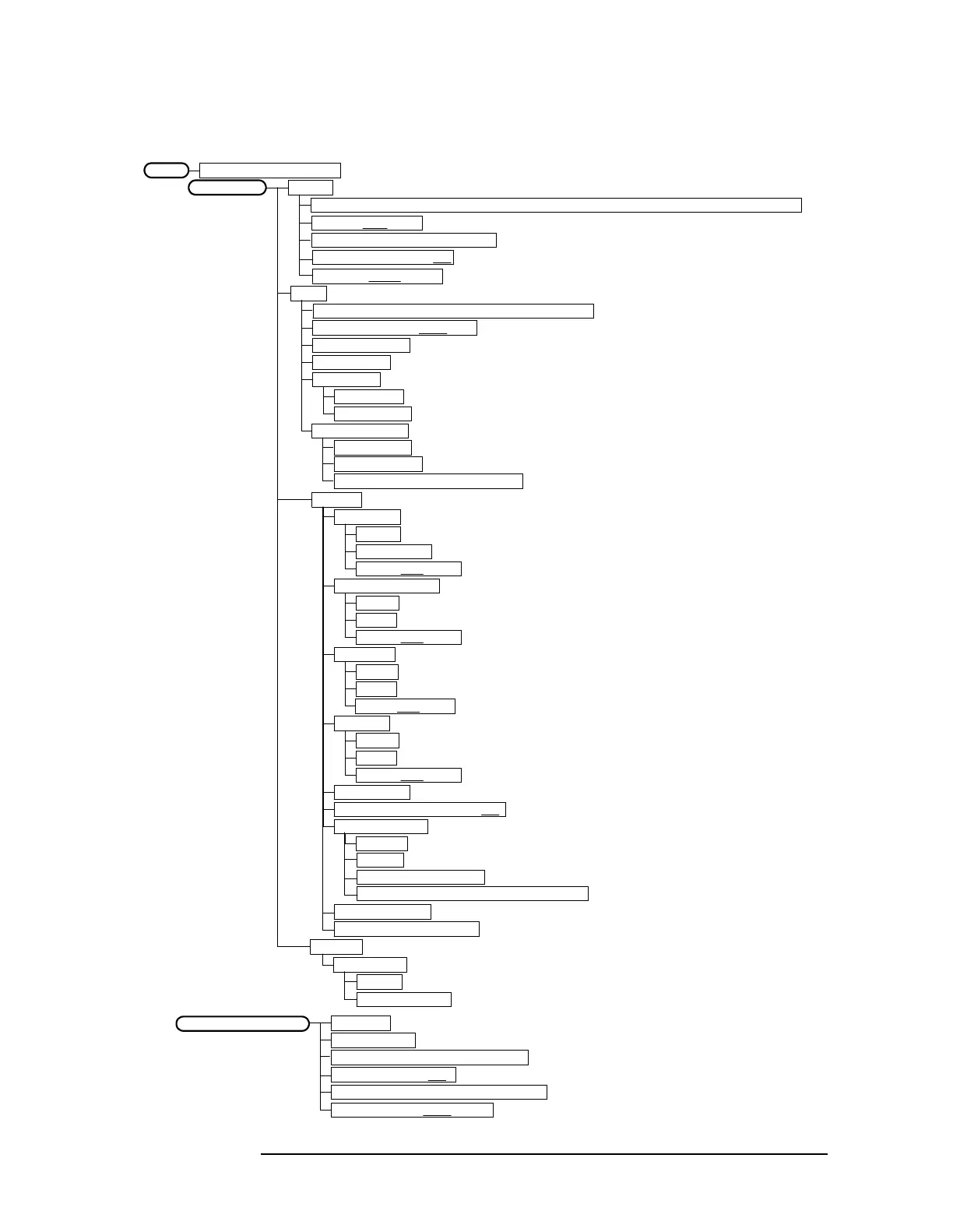
Figure 2-1 Mode Setup / Frequency Channel Key Flow
Radio
Band P-GSM, E-GSM, R-GSM, DCS 1800, PCS 1900, GSM 450, GSM 480, GSM 850
Device BTS | MS
Input
RF Input Range Auto| Man
Max Total Pwr
Input Atten
Ext Atten
MS 0.00 dB
BTS 0.00 dB
Trigger
RF Burst
Delay
Peak Level
Slope Pos | Neg
Video (IF Envlp)
Delay
Level
Slope Pos | Neg
Ext Front
Delay
Level
Slope Pos | Neg
Ext Rear
Delay
Level
Slope Pos | Neg
Trig Holdoff
Auto Trig 100.0 ms On | Off
Frame Timer
Period
ARFCN
Center Freq
BTM Freq Top, Middle, Bottom
Timeslot On | Off
Burst Type Normal, Sync, Access
Mode Setup
Frequency Channel
<Auto not for Spectrum>
<for EVM when Device is MS>
GSM or EDGE w/GSMMode
Freq Hopping On |Off
Carrier Burst | Cont
Offset
Reset Offset Display
Sync Source Off, Ext Front, Ext Rear
RF Sync Delay
Burst SearchThreshold
Input Port RF, I/Q, I only, 50 MHz Ref, IF Align
IF Align Signal
Signal Rate
Signal Amptd
Signal Type CW, Comb, Pulse
Demod
Burst Align
GSM
1/2 Bit Offset
TSC (Std) 0 Auto | Man
BTS Type Normal, Micro, Pico
<Available for RF only>
<Available for RF and 50 MHz Ref only>

 Loading...


