3 Adjustments
66 E4416A/E4417A Power Meters Service Guide
For this adjustment the following mathematical assumptions are made:
Equation 1:
can be manipulated to give the following:
Equation 2:
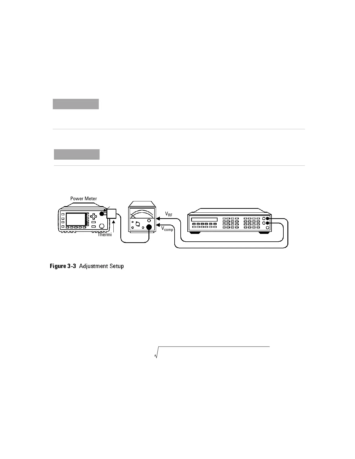
To ensure maximum accuracy in re-adjusting the power reference oscillator output, this
procedure provides step-by-step instructions for using Agilent test instruments of
known capability. Signal acquisition criteria may vary if alternative test instruments are
used. In such cases refer to the manufacturer's guidelines for further information.
The power meter may be returned to the nearest Agilent Technologies office to have
the power reference oscillator checked and/or adjusted.
Figure 3-3
Adjustment Setup
Power Meter
V
RF
V
comp
Thermistor
mount
Power ref
Digital Voltmeter
+ input
Agilent 432A
Power Meter
− input
P
meas
2V
comp
V
1
V
0
–()V
0
2
V
1
2
–+
4R CalibrationF actor()
-------------------------------------------------------------------=
V
1
V
com p
V
0
V
comp
2
10()
3–
4R()CalibrationFactor()––+=
Artisan Technology Group - Quality Instrumentation ... Guaranteed | (888) 88-SOURCE | www.artisantg.com