Replaceable Parts 5
E4416A/E4417A Power Meters Service Guide 97
Removing the A2 Processor Assembly
1 Remove the A5 daughter and A6 measurement assemblies as described on
page 101.
2 Move the A2 plastic support bracket to its forward position using the two
side levers, unclip the flexi- cable retaining bar on the front panel keypad
and front panel LCD cable connectors and disconnect the cable.
3 Disconnect the following cables from the A2 processor assembly:
• Power reference semi- rigid.
• Fan connector.
• Power supply connector.
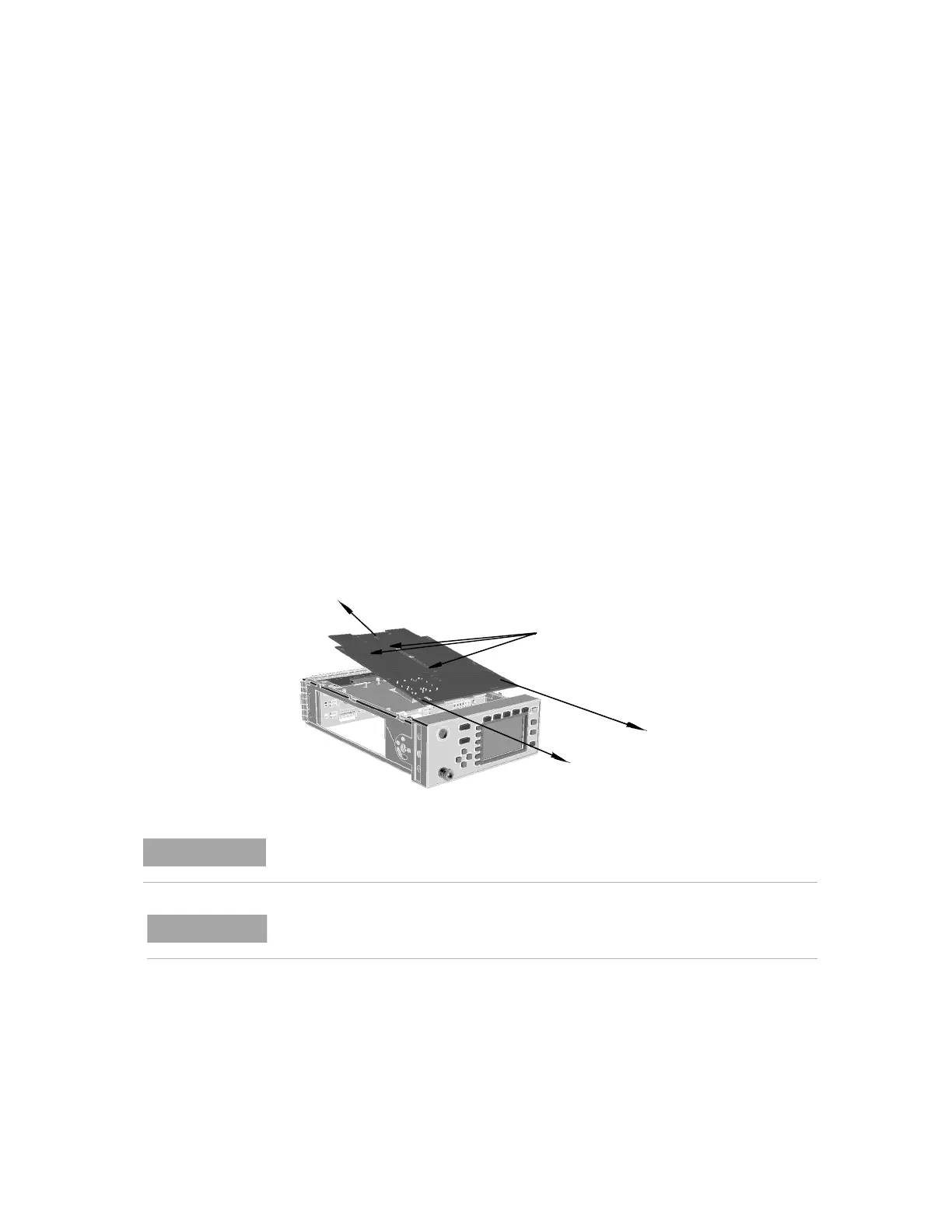
4 Turn the power meter upside down and remove the three screws as shown.
When replacing these screws use a 6 lb/in T10 screw driver.
5 Push the A2 processor assembly towards the front panel to release it from
the 50- pin connector. Lift it upwards to remove.
When re-assembling the processor board, ensure the A2 plastic support bracket is
returned to its locked position.
After replacing a processor board, the Power Reference Frequency and Level must be
checked. For further information refer to Chapter 2, “Performance Test Record”.
Artisan Technology Group - Quality Instrumentation ... Guaranteed | (888) 88-SOURCE | www.artisantg.com