Replaceable Parts 5
E4416A/E4417A Power Meters Service Guide 99
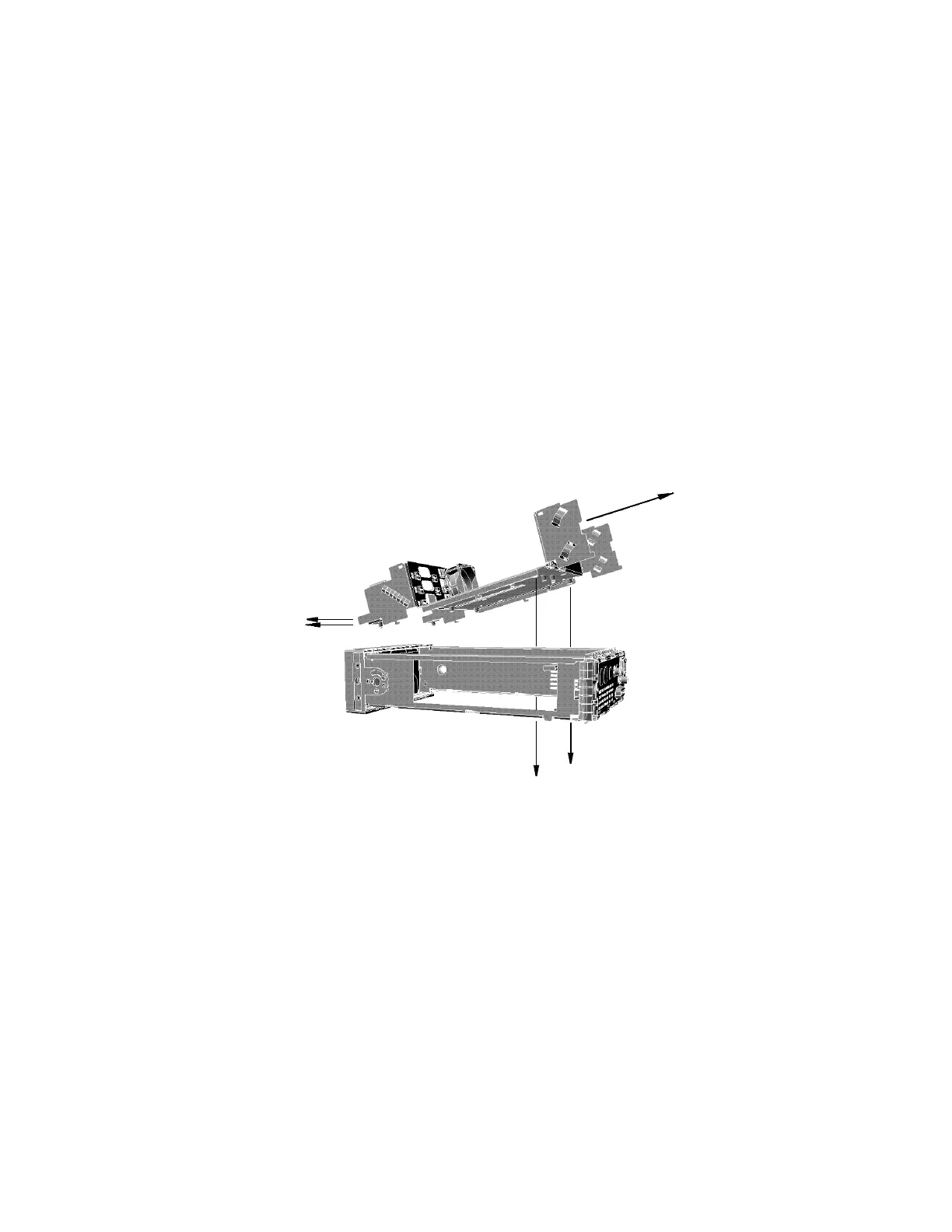
Removing the A4 Comms Assembly
1 Remove the A2 processor, A5 daughter and A6 measurement assemblies as
shown on page 97 and page 101.
2 Disconnect the line power module from the A1 power supply and the
chassis.
3 Disconnect the earth wire screw. When replacing this screw use a 9 lb/in
T15 screw driver.
4 Remove the two screws on the underside of the deck assembly. Remove the
assembly by sliding forward and tilting up from the rear. When replacing
these screws use a 21 lb/in T15 screw driver.
5 Unscrew the GPIB and RS232/422 connectors from the rear panel. When
replacing these screws use a 6 lb/in 9/32 in socket.
6 Disconnect the Recorder cable for channel A from J23 pins 1,2,3.
Disconnect the Recorder cable for channel B from J23 pins 4,5,6.
7 Lift the A4 Comms assembly from the two standoffs and slide it out.
Artisan Technology Group - Quality Instrumentation ... Guaranteed | (888) 88-SOURCE | www.artisantg.com