Installing the GC 1
Agilent Intuvo 9000 GC Installation 55
Materials needed:
• 1/4-inch insulated copper tubing
Procedure:
1 Position the nitrogen tank as close to the GC as possible to
insure that liquid and not gas is delivered to the inlet.
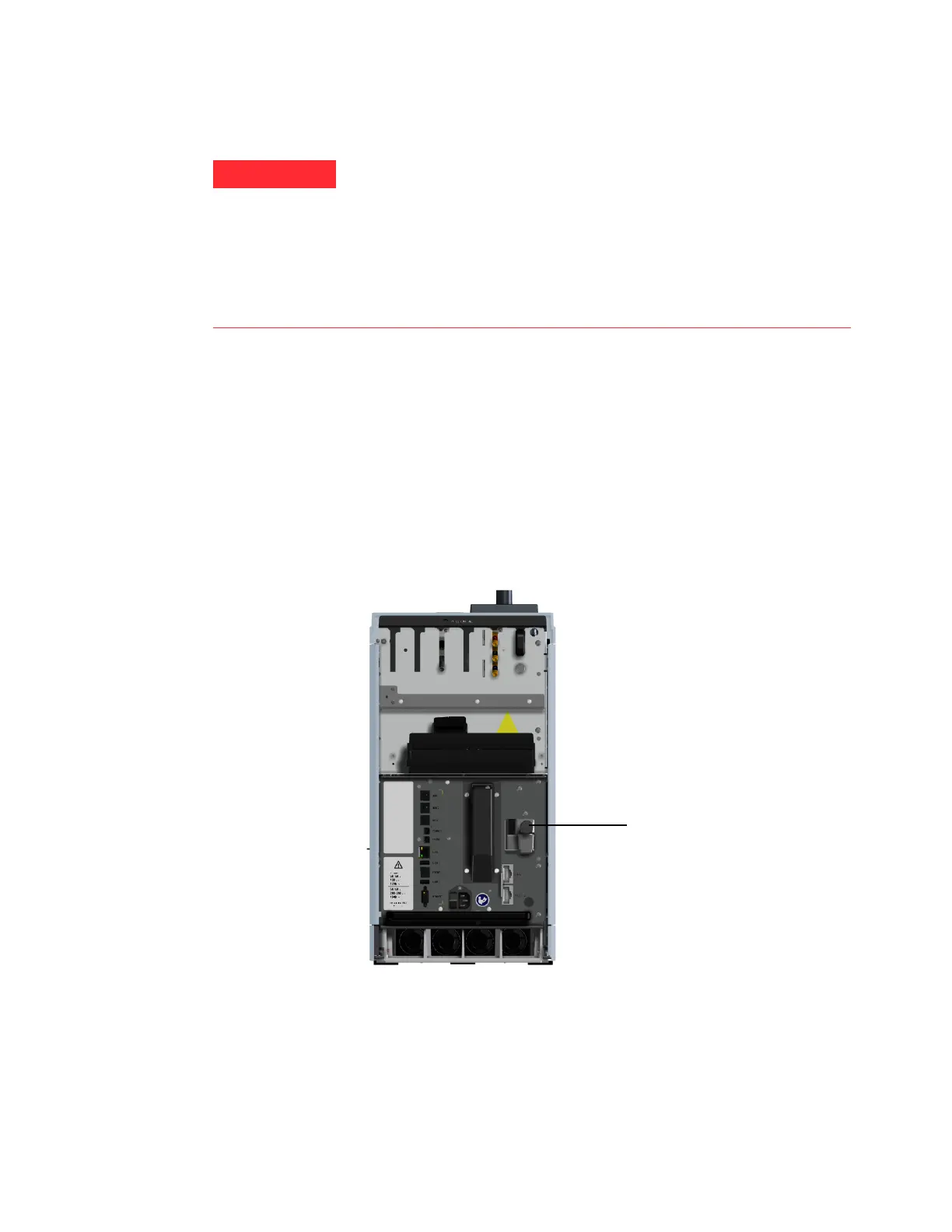
2 Locate the inlet for coolant on the back of the GC. Prepare
enough tubing to reach from the supply tank to this outlet.
3 Connect the supply tubing to the liquid N2 tank outlet with
the fitting recommended by the supplier.
4 Use a Swagelok fitting to connect the supply tubing to the
cryogenic valve inlet.
If liquid nitrogen is trapped between a closed tank valve and the
cryo valve on the GC, tremendous pressure will develop and may
cause an explosion. For this reason, keep the delivery valve on
the tank open so that the entire system is protected by the
pressure relief valve.
To move or replace a tank, close the delivery valve and carefully
disconnect the line at either end to let residual nitrogen escape.
,QOHWFU\RFRROLQJÀWWLQJ
 Loading...