74 Agilent Intuvo 9000 GC Installation
1 Installing the GC
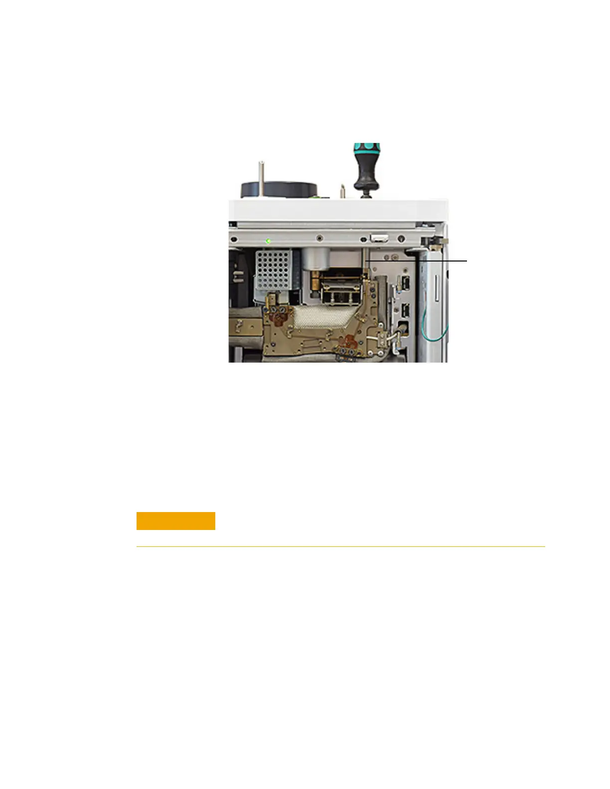
chip compression bolt through the top of the GC as shown
below.) See Figure 13.
Figure 13 Loosening the Guard chip compression bolt (split/splitless
inlet shown)
d Use the torque driver to open the clips that secure the
inlet chip to the bus. See Figure 10.
e Orient the new inlet chip. Slide the bottom connector of
the inlet chip behind the Smart ID connector wire for the
detector chip, and insert the bottom connector into the
column fitting on the bus. Then, insert the top connector
into the pocket in the little bus. See Figure 10.
f Seat the chip's column connector into the column fitting.
g Check your work. Both click and run connectors should be
centered in their fittings, the chip's connector in the
Intuvo torque
driver shaft
Make sure the connectors are fully seated in the column fitting and
little bus.

 Loading...