EasyManuals Logo
Home>Agilent Technologies>Laboratory Equipment>Intuvo 9000

Agilent Technologies Intuvo 9000 User Manual

Agilent Technologies Intuvo 9000
114 pages
To Next Page IconTo Next Page
To Previous Page IconTo Previous Page
Page #77 background imageLoading...
Page #77 background image
Installing the GC 1
Agilent Intuvo 9000 GC Installation 77
e
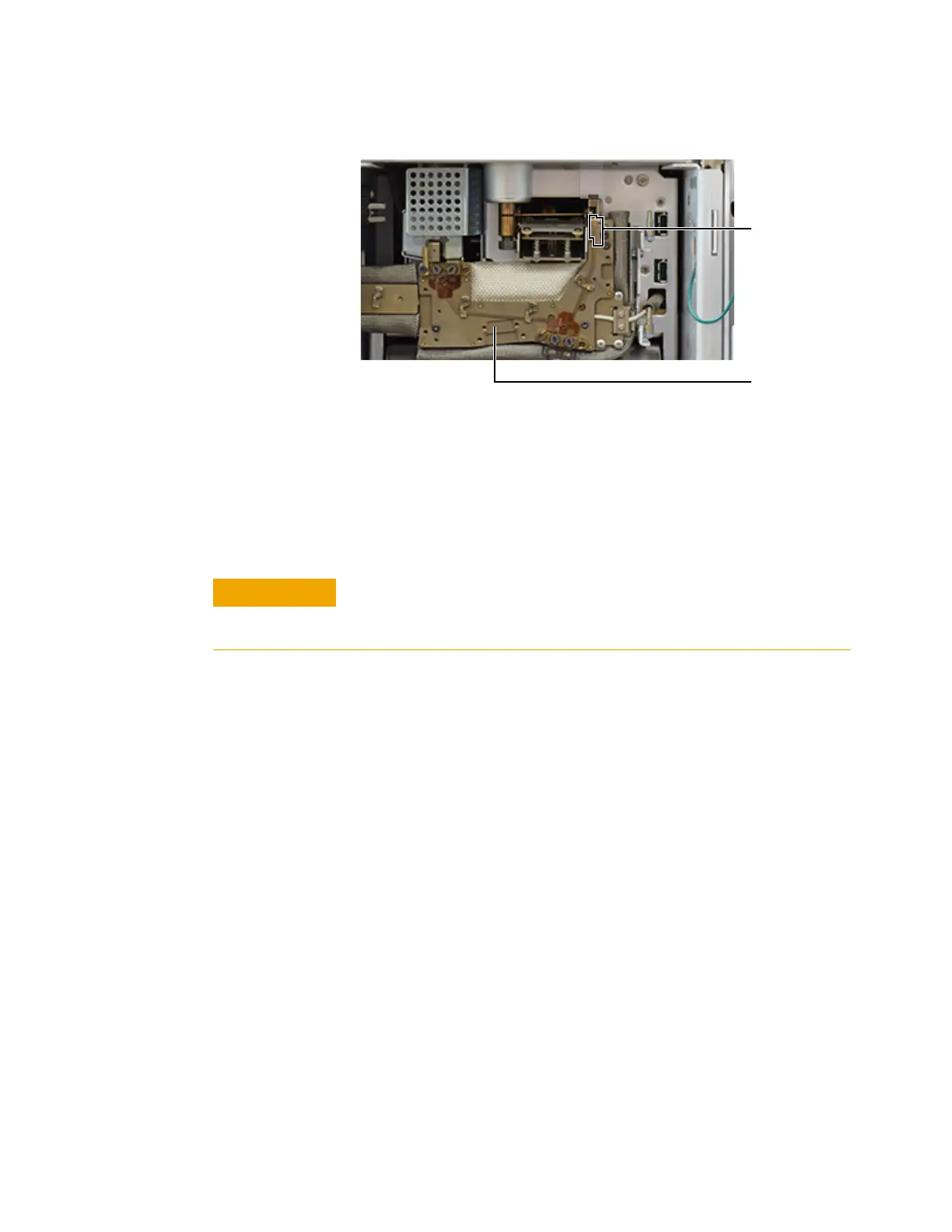
Check Guard chip placement. The Guard chip should be
level between the inlet and little bus. You should no longer
see the entire neck of the Guard chip if it is seated
properly, as a portion of it will be obscured by the heater
block. If not, reseat it.
f Finger-tighten the Guard chip compression bolt until you
feel slight contact on the Guard chip.
g Gently raise the Guard chip heater.
h Finger-tighten the inlet sealing screw.
i Tighten the inlet sealing screw. For MMI, use two
wrenches. (See the figure below.)
Little bus
Bus
CAUTION
To avoid damaging the Guard chip, do not raise the Guard chip
heater until after you finger-tighten the Guard chip compression
bolt.

Table of Contents

Other manuals for Agilent Technologies Intuvo 9000

Questions and Answers:

Question and Answer IconNeed help?

Do you have a question about the Agilent Technologies Intuvo 9000 and is the answer not in the manual?

Agilent Technologies Intuvo 9000 Specifications

General IconGeneral
BrandAgilent Technologies
ModelIntuvo 9000
CategoryLaboratory Equipment
LanguageEnglish

Related product manuals