K65C/K75C/K95C
8-15
K65C/K75C/K95C
8-15
2
1
2
1
CAUTION
The bearing bolts of the multi-purpose
bucket (8-29/arrows) must be lubri-
cated every 10 operating hours.
NOTE
The bolts must be lubricated on both
sides of the multi-purpose bucket.
8.2.15 Replacing the starter
battery
NOTE
The starter battery is a maintenance-
free part according to DIN 72311,
section 7. It is located beneath the
maintenance plate to the left of the
driver's seat.
(1) Remove the battery main switch
(4-11/3).
(2) Remove the insulation mat to
the left of the driver's seat.
(3) Loosen the fastening screws
(8-30/arrows) (size 13) and remove
the maintenance plate.
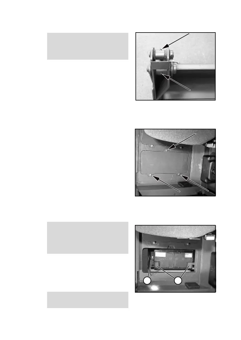
(4) Loosen and remove the
fastening screw (8-31/1) (size 17) of
the battery holder.
(5) Fold up the cover caps (8-31/2)
and disconnect and remove the
terminals from the battery (size 13).
DANGER
Always remove the negative
terminal first and then the positive
terminal. Installation is in the reverse
order.
(6) Remove the battery and
replace it.
(7) Apply grease to the terminals
before fastening them.
(8) Installation is in the reverse
order.
DANGER
Make sure the fastenings are secure.
Figure 8-30
Figure 8-31
Figure 8-29
CAUTION
The bearing bolts of the multi-purpose
bucket (8-29/arrows) must be lubri-
cated every 10 operating hours.
NOTE
The bolts must be lubricated on both
sides of the multi-purpose bucket.
8.2.15 Replacing the starter
battery
NOTE
The starter battery is a maintenance-
free part according to DIN 72311,
section 7. It is located beneath the
maintenance plate to the left of the
driver's seat.
(1) Remove the battery main switch
(4-11/3).
(2) Remove the insulation mat to
the left of the driver's seat.
(3) Loosen the fastening screws
(8-30/arrows) (size 13) and remove
the maintenance plate.
(4) Loosen and remove the
fastening screw (8-31/1) (size 17) of
the battery holder.
(5) Fold up the cover caps (8-31/2)
and disconnect and remove the
terminals from the battery (size 13).
DANGER
Always remove the negative
terminal first and then the positive
terminal. Installation is in the reverse
order.
(6) Remove the battery and
replace it.
(7) Apply grease to the terminals
before fastening them.
(8) Installation is in the reverse
order.
DANGER
Make sure the fastenings are secure.
Figure 8-30
Figure 8-31
Figure 8-29