6-2
K65C/K75C/K95C
6-2
K65C/K75C/K95C
Dismounting
(1) Place the bucket firmly on the
ground.
(2) Press the release button for
the quick-change device (4-13/2)
and, while keeping the button
depressed, unlock the bucket by
using the hand lever for the auxiliary
hydraulics (4-12/1).
(3) Tilt the quick-change device
and reverse out.
CAUTION
The hydraulic quick-change device
must only be locked when an
attachment has been mounted.
NOTE
The type plate is on the rear of the
bucket, on the right-hand side below
the cross arm.
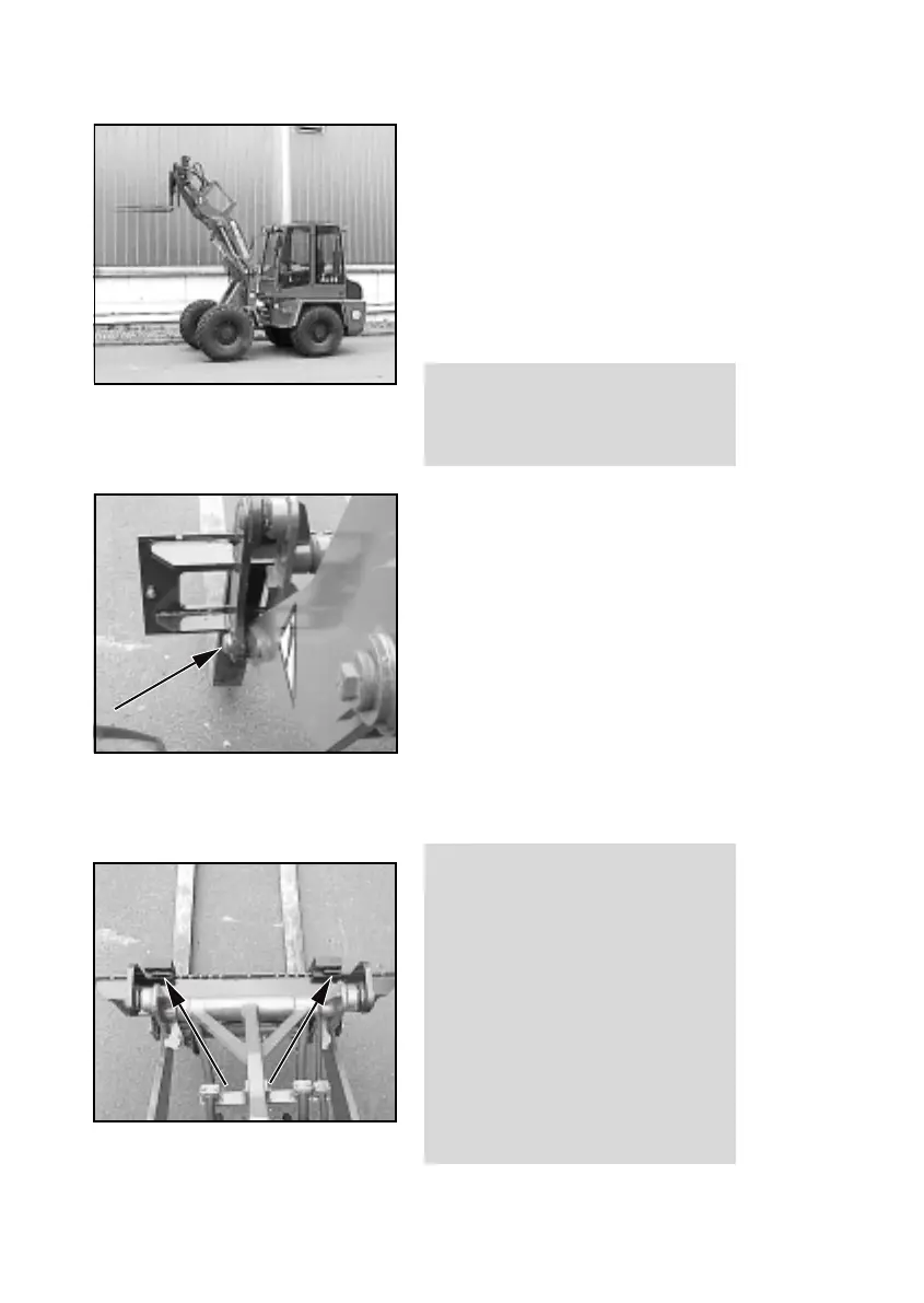
6.1.2 Fork-lift attachment
NOTE
- Figure 6-4 shows the loader with
the fork-lift attachment in the
topmost bucket arm position.
- Mounting and dismounting are
carried out in the same way as for
the standard/lightweight bucket
(section 6.1.1).
DANGER
- The two bolts of the quick-change
device must be in the bore holes
of the fork-lift attachment suspen-
sion and must be clearly visible
(6-5/arrow).
- Distribute the load equally on both
fork tines and secure it against
moving and falling off.
- Let the load rest against the rear
of the fork and tilt the fork-lift
attachment.
- Position both fork tines at an equal
distance from the centre (6-6/
arrows) and lock them.
Figure 6-5
Figure 6-6
Figure 6-4
Figure 6-5
Figure 6-6
Figure 6-4
Dismounting
(1) Place the bucket firmly on the
ground.
(2) Press the release button for
the quick-change device (4-13/2)
and, while keeping the button
depressed, unlock the bucket by
using the hand lever for the auxiliary
hydraulics (4-12/1).
(3) Tilt the quick-change device
and reverse out.
CAUTION
The hydraulic quick-change device
must only be locked when an
attachment has been mounted.
NOTE
The type plate is on the rear of the
bucket, on the right-hand side below
the cross arm.
6.1.2 Fork-lift attachment
NOTE
- Figure 6-4 shows the loader with
the fork-lift attachment in the
topmost bucket arm position.
- Mounting and dismounting are
carried out in the same way as for
the standard/lightweight bucket
(section 6.1.1).
DANGER
- The two bolts of the quick-change
device must be in the bore holes
of the fork-lift attachment suspen-
sion and must be clearly visible
(6-5/arrow).
- Distribute the load equally on both
fork tines and secure it against
moving and falling off.
- Let the load rest against the rear
of the fork and tilt the fork-lift
attachment.
- Position both fork tines at an equal
distance from the centre (6-6/
arrows) and lock them.