5-8
K65C/K75C/K95C
5-8
K65C/K75C/K95C
Figure 5-6
Figure 5-7
CAUTION
If the control lamp for the hydraulic
oil temperature (4-13/25) lights up
during operation, the loader must
be switched off immediately, the
cause must be determined by a
hydraulics expert and the mal-
function must be eliminated.
5.2.5 Heating and venti-
lation system
5.2.5.1 Adjusting the amount
of air
(1) Turn the rotary switch (5-5/
arrow) for the blower to position 0,
1 or 2, depending on the amount of
air desired.
(2) Adjust the direction of the air
flow by means of the lateral nozzles
(5-6/arrow).
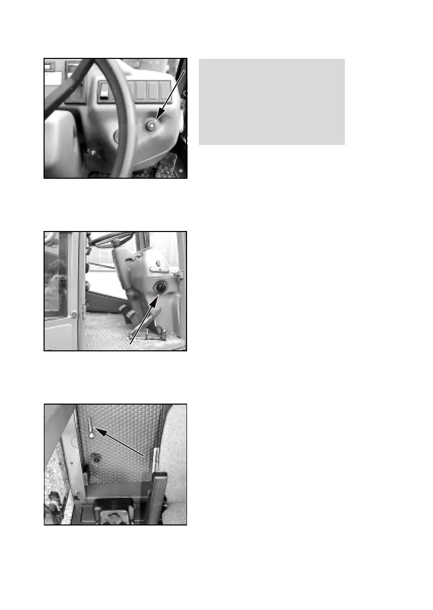
5.2.5.2Switching on the
heater
(1) Depending on the heat
required, turn the ball valve lever
(5-7/arrow) to the front or to the
side.
NOTE
Lever to the front - warm.
Lever to the side - cold.
(2) Adjust the amount of air as
described under 5.2.5.1.
Figure 5-5
Figure 5-6
Figure 5-7
Figure 5-5
CAUTION
If the control lamp for the hydraulic
oil temperature (4-13/25) lights up
during operation, the loader must
be switched off immediately, the
cause must be determined by a
hydraulics expert and the mal-
function must be eliminated.
5.2.5 Heating and venti-
lation system
5.2.5.1 Adjusting the amount
of air
(1) Turn the rotary switch (5-5/
arrow) for the blower to position 0,
1 or 2, depending on the amount of
air desired.
(2) Adjust the direction of the air
flow by means of the lateral nozzles
(5-6/arrow).
5.2.5.2Switching on the
heater
(1) Depending on the heat
required, turn the ball valve lever
(5-7/arrow) to the front or to the
side.
NOTE
Lever to the front - warm.
Lever to the side - cold.
(2) Adjust the amount of air as
described under 5.2.5.1.