6-4
K65C/K75C/K95C
6-4
K65C/K75C/K95C
Figure 6-9
Figure 6-10
6.2 Mounting and dis-
mounting attachments with
a hydraulic connection
6.2.1 Multi-purpose bucket
Mounting
(1) Bring the bucket arm to its
lowest position and tip the quick-
change device.
(2) Drive the loader up to the
bucket (6-9).
(3) Pick up the bucket using the
quick-change device and, by
simultaneously tilting the quick-
change device, raise the bucket
until the quick-change device is next
to it (6-10).
(4) Lock the bucket by using the
hand lever for the auxiliary hy-
draulics (4-12/1).
(5) Check the connection and the
lock on both sides.
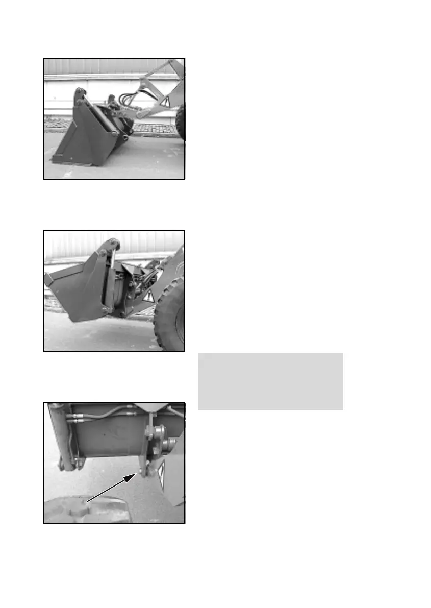
DANGER
The two bolts of the quick-change
device must be in the bore holes of
the bucket suspension and must
be clearly visible (6-11/arrow).
(6) Stop the engine.
(7) Remove the pressure from the
hydraulic lines. For this purpose,
move the hand lever for the auxiliary
hydraulics (4-12/1) back and forth
several times.
Figure 6-11
Figure 6-9
Figure 6-10
6.2 Mounting and dis-
mounting attachments with
a hydraulic connection
6.2.1 Multi-purpose bucket
Mounting
(1) Bring the bucket arm to its
lowest position and tip the quick-
change device.
(2) Drive the loader up to the
bucket (6-9).
(3) Pick up the bucket using the
quick-change device and, by
simultaneously tilting the quick-
change device, raise the bucket
until the quick-change device is next
to it (6-10).
(4) Lock the bucket by using the
hand lever for the auxiliary hy-
draulics (4-12/1).
(5) Check the connection and the
lock on both sides.
DANGER
The two bolts of the quick-change
device must be in the bore holes of
the bucket suspension and must
be clearly visible (6-11/arrow).
(6) Stop the engine.
(7) Remove the pressure from the
hydraulic lines. For this purpose,
move the hand lever for the auxiliary
hydraulics (4-12/1) back and forth
several times.
Figure 6-11