K65C/K75C/K95C
6-5
K65C/K75C/K95C
6-5
2
1
2
1
2
1
2
1
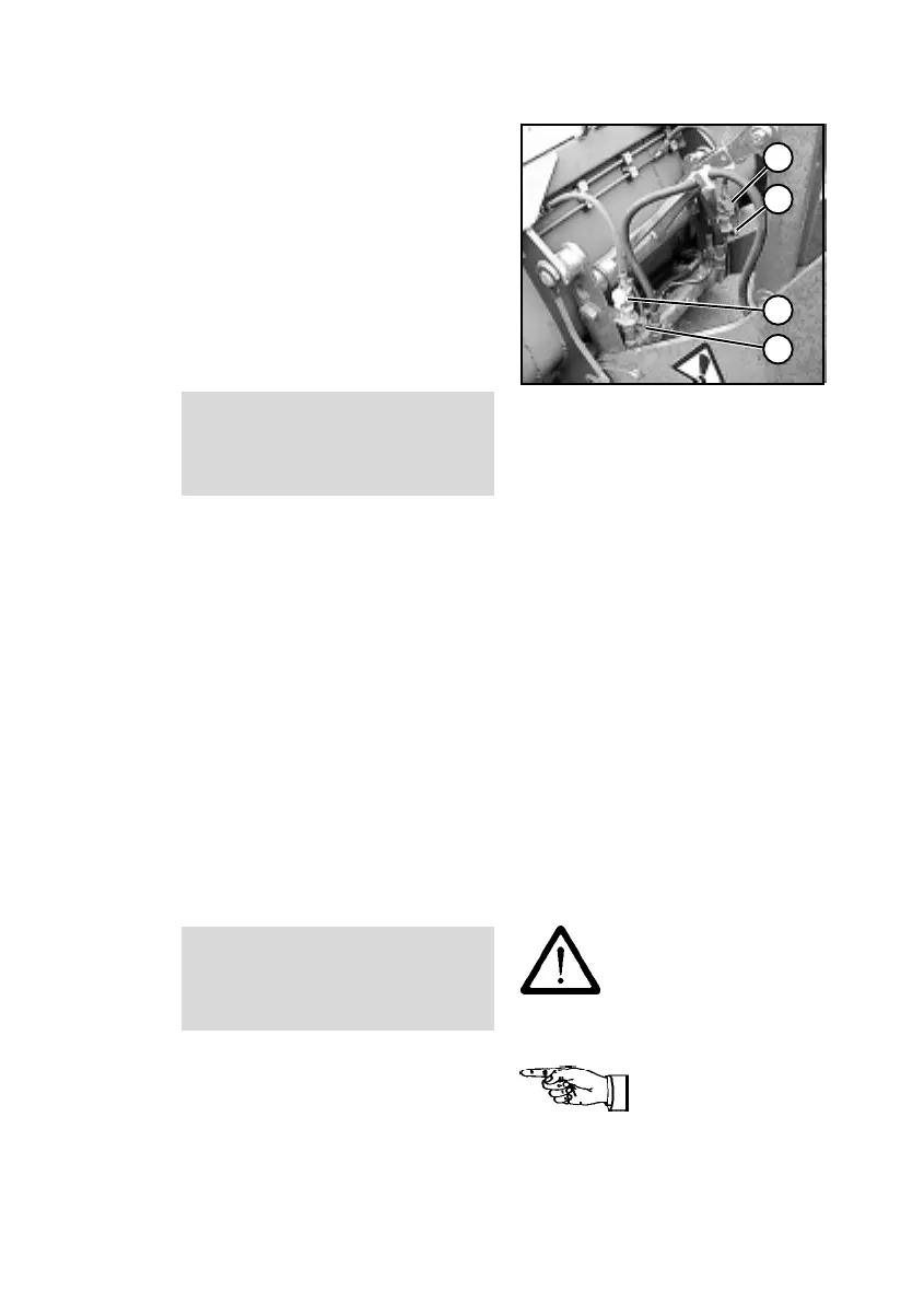
(8) Remove the protective caps
from the hoses of the multi-purpose
bucket (6-12/1).
(9) Swing up the protective flaps
of the quick-action couplings of the
quick-change device (6-12/2) and
connect the hydraulic hoses of the
multi-purpose bucket with the quick-
action couplings of the quick-
change device by pushing them
firmly in (6-12).
CAUTION
When making connections, make
sure that the hydraulic connections
are clean and completely connected.
Dismounting
(1) Place the multi-purpose
bucket firmly on the ground.
(2) Stop the engine.
(3) Remove the pressure from the
hydraulic lines. For this purpose,
move the hand lever for the auxiliary
hydraulics (4-12/1) back and forth
several times.
(4) Dismounting takes place in the
reverse order of mounting. How-
ever, to unlock the multi-purpose
bucket, the release button for the
quick-change device (4-13/2) must
be used.
CAUTION
The hydraulic quick-change device
must only be locked when an
attachment has been mounted.
NOTE
The type plate is on the rear of the
bucket, on the right-hand side
beneath the cross arm.
Figure 6-12 Figure 6-12
(8) Remove the protective caps
from the hoses of the multi-purpose
bucket (6-12/1).
(9) Swing up the protective flaps
of the quick-action couplings of the
quick-change device (6-12/2) and
connect the hydraulic hoses of the
multi-purpose bucket with the quick-
action couplings of the quick-
change device by pushing them
firmly in (6-12).
CAUTION
When making connections, make
sure that the hydraulic connections
are clean and completely connected.
Dismounting
(1) Place the multi-purpose
bucket firmly on the ground.
(2) Stop the engine.
(3) Remove the pressure from the
hydraulic lines. For this purpose,
move the hand lever for the auxiliary
hydraulics (4-12/1) back and forth
several times.
(4) Dismounting takes place in the
reverse order of mounting. How-
ever, to unlock the multi-purpose
bucket, the release button for the
quick-change device (4-13/2) must
be used.
CAUTION
The hydraulic quick-change device
must only be locked when an
attachment has been mounted.
NOTE
The type plate is on the rear of the
bucket, on the right-hand side
beneath the cross arm.
 Loading...