4-8
K65C/K75C/K95C
4-8
K65C/K75C/K95C
4.3 Changing a wheel
DANGER
Before changing a wheel on public
roads, the danger area must be
properly marked.
(1) Park the loader on solid ground
and not on inclines if possible.
(2) Lower the attachment to the
ground.
(3) Set the drive switch (4-12/6)
to “0”.
(4) Apply the parking brake
(4-12/3).
(5) Turn the ignition key to the left
to position “0” (5-1).
(6) Close the ball block valve for
the working and auxiliary hydraulics
(1-3/arrow).
(7) Insert the articulation safe-
guard into the articulation joint
(1-4/arrow).
(8) Secure the machine by placing
two wedges under one wheel of the
axle where no wheel is to be
changed.
(9) Loosen the wheel nuts of the
wheel to be changed so that they
can be turned manually.
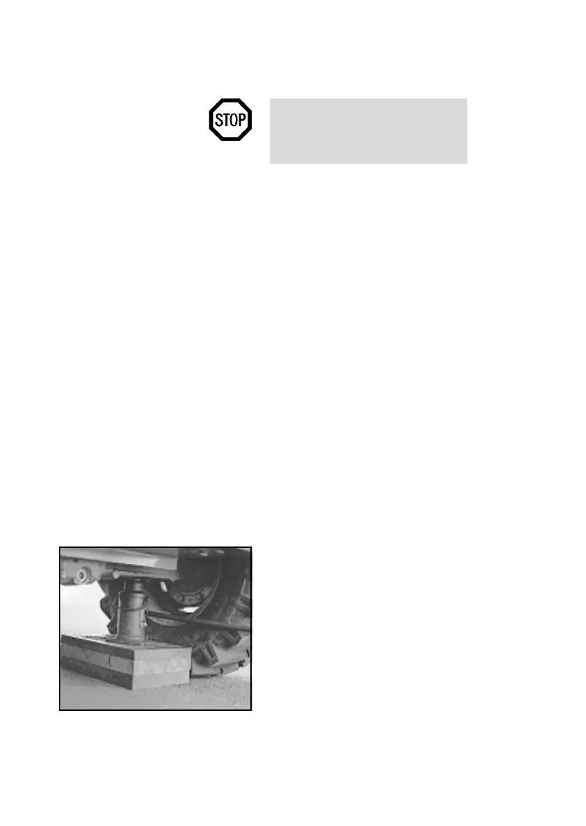
(10) Fit a suitable jack (minimum
capacity 3.0 tons) from the side
under the axle bridge in the vicinity
of the axle fixture so that it is centred
and cannot slip (4-9). Lift the front/
rear axle until the wheel does not
have any contact to the ground.
Figure 4-9
4.3 Changing a wheel
DANGER
Before changing a wheel on public
roads, the danger area must be
properly marked.
(1) Park the loader on solid ground
and not on inclines if possible.
(2) Lower the attachment to the
ground.
(3) Set the drive switch (4-12/6)
to “0”.
(4) Apply the parking brake
(4-12/3).
(5) Turn the ignition key to the left
to position “0” (5-1).
(6) Close the ball block valve for
the working and auxiliary hydraulics
(1-3/arrow).
(7) Insert the articulation safe-
guard into the articulation joint
(1-4/arrow).
(8) Secure the machine by placing
two wedges under one wheel of the
axle where no wheel is to be
changed.
(9) Loosen the wheel nuts of the
wheel to be changed so that they
can be turned manually.
(10) Fit a suitable jack (minimum
capacity 3.0 tons) from the side
under the axle bridge in the vicinity
of the axle fixture so that it is centred
and cannot slip (4-9). Lift the front/
rear axle until the wheel does not
have any contact to the ground.
Figure 4-9