K65C/K75C/K95C
7-3
K65C/K75C/K95C
7-3
1
2
1
a
b
3
2
1
2
1
2
1
a
b
3
2
1
2
Figure 7-4
Figure 7-3
Figure 7-2
(8) Insert the bucket arm support
(1-1/arrow) and lower the bucket
arm onto the bucket arm support.
(9) Close the ball block valve
(1-3/arrow) for the working and
auxiliary hydraulics.
(10) Attach the tow-bar to the loader
to be towed (7-2/2) and to the towing
vehicle.
(11) Release the parking brake
lever (4-12/3).
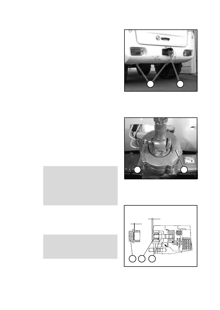
(12) Release the brake. To do so,
remove both screw plugs (7-3/1
and 7-3/2) from the housing (size
24).
NOTE
- The tools required are contained
in the tool kit.
- Screw plug 7-3/2 has already
been removed.
- Collect any oil that escapes.
(13) Remove the sleeves (7-3/2
and 7-4/2) from the setscrews.
(14) Tighten the lock nuts (7-4/3)
(size 19).
CAUTION
The lock nuts must be tightened
synchronously, i.e. tightening must
be carried out in steps of half a
revolution that are repeated syn-
chronously for the two nuts to pre-
vent the piston from getting jammed.
(15) Push the sleeves (7-3/2 and
7-4/2) onto the setscrews again.
(16) Screw in the screw plugs with
an O-ring into the housing.
CAUTION
After towing has been completed,
restore the operating state of the
brake.
Figure 7-4
Figure 7-3
Figure 7-2
(8) Insert the bucket arm support
(1-1/arrow) and lower the bucket
arm onto the bucket arm support.
(9) Close the ball block valve
(1-3/arrow) for the working and
auxiliary hydraulics.
(10) Attach the tow-bar to the loader
to be towed (7-2/2) and to the towing
vehicle.
(11) Release the parking brake
lever (4-12/3).
(12) Release the brake. To do so,
remove both screw plugs (7-3/1
and 7-3/2) from the housing (size
24).
NOTE
- The tools required are contained
in the tool kit.
- Screw plug 7-3/2 has already
been removed.
- Collect any oil that escapes.
(13) Remove the sleeves (7-3/2
and 7-4/2) from the setscrews.
(14) Tighten the lock nuts (7-4/3)
(size 19).
CAUTION
The lock nuts must be tightened
synchronously, i.e. tightening must
be carried out in steps of half a
revolution that are repeated syn-
chronously for the two nuts to pre-
vent the piston from getting jammed.
(15) Push the sleeves (7-3/2 and
7-4/2) onto the setscrews again.
(16) Screw in the screw plugs with
an O-ring into the housing.
CAUTION
After towing has been completed,
restore the operating state of the
brake.