7-8
K65C/K75C/K95C
7-8
K65C/K75C/K95C
D
A
2
C
2
D
B
A
1
C
1
D
A
2
C
2
D
B
A
1
C
1
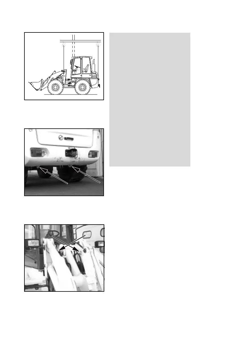
CAUTION
The following items must be
observed when lifting the loader by
crane (Figure 7-8):
- The lifting point (A
1
- loader with-
out standard bucket or A
2
- loader
with standard bucket) of the lifting
device (B) must be precisely ver-
tically over the centre of gravity
(C
1
or C
2
) of the loader so that the
lifting device is horizontally
above the longitudinal axis of the
loader.
- The lifting gear (D) must lead ver-
tically upwards from the lifting
points of the loader (7-9/arrows
and 7-10/arrows).
DANGER
The lifting gear must have a lifting
capacity of at least 3.0 t.
Figure 7-8
Figure 7-10
Figure 7-9