Rockwell Automation Publication 2094-UM001J-EN-P - March 2017 209
Interconnect Diagrams Appendix A
Table 114 - MP-Series Electric Cylinder Power and Feedback Cables
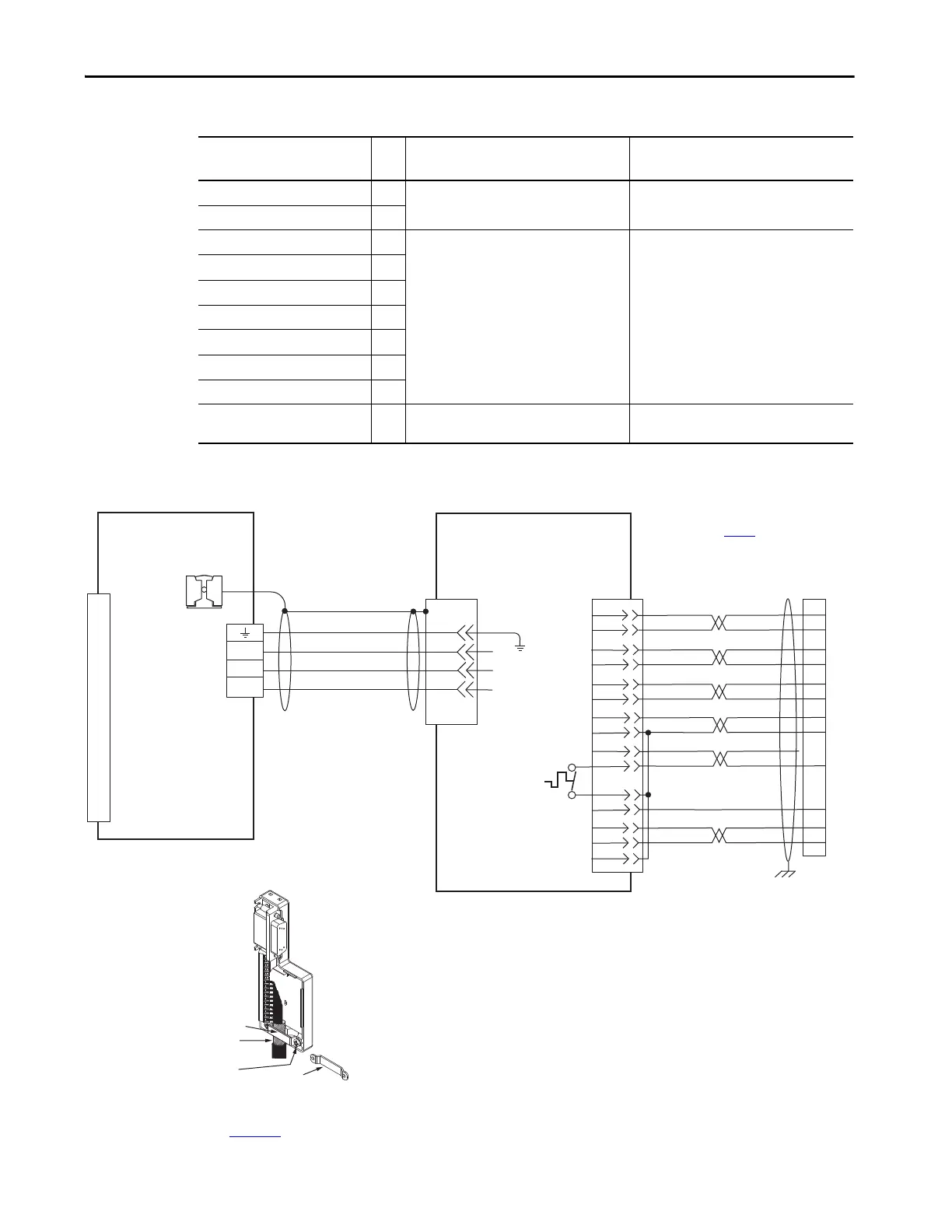
Figure 106 - AM Module with LDAT-Series Linear Thrusters
MP-Series Electric Cylinder
Cat. No.
Frame
Power Cable
Cat. No.
Feedback Cable
Cat. No.
MPAR-A/B1xxx (series A)
(1)
32
2090-XXNPMF-16Sxx (standard) or
2090-CPxM4DF-16AFxx (continuous-flex)
2090-XXNFMF-Sxx (standard) or
2090-CFBM4DF-CDAFxx (continuous-flex)
MPAR-A/B2xxx (series A) 40
MPAR-A/B1xxx (series B) 32
2090-CPxM7DF-16AAxx (standard) or
2090-CPxM7DF-16AFxx (continuous-flex)
2090-CFBM7DF-CEAAxx (standard) or
2090-CFBM7DF-CEAFxx (continuous-flex)
MPAR-A/B2xxx (series B) 40
MPAR-A/B3xxx 63
MPAI-A/B2xxxx 64
MPAI-A/B3xxxx 83
MPAI-A/B4xxxx 110
MPAI-B5xxxx 144
MPAI-A5xxxx 144
2090-CPxM7DF-14AAxx (standard) or
2090-CPxM7DF-14AFxx (continuous-flex)
2090-CFBM7DF-CEAAxx (standard) or
2090-CFBM7DF-CEAFxx (continuous-flex)
(1) Bulletin MPAR (series A) electric cylinders have threaded (M4) connectors and require threaded (M4) cable connectors.
D
C
B
A
W
V
U
4
3
2
1
Green/Yellow
Blue
Black
Brown
GND
Shield
W
V
U
AM+
AM-
BM+
BM-
IM+
IM-
+5VDC
ECOM
WHITE/BLUE
GREEN
WHITE/GREEN
GRAY
WHITE/GRAY
BLACK
WHITE/BLACK
RED
WHITE/RED
1
2
3
4
5
10
14
6
12
S1
–
TS
ORANGE
WHITE/ORANGE
11
S2
S3
YELLOW
WHITE/YELLOW
13
8
3
4
5
6
1
2
14
15
16
17
12
11
13
9
10
COM
1
2
3
4
5
6
7
8
9
10
11
12
13
14
15
Motor Power
(MP) Connector
Cable Shield
Clamp
Note 10
Note 15
LDAT-Sxxxxxx-xBx
Linear Thrusters with
Incremental Feedback
Three-phase
Motor Power
Motor
Feedback
Thermostat
Refer to low-profile connector
illustration (lower left)
for proper grounding technique.
Grounding Technique for
Feedback Cable Shield
Turn clamp over to hold
small cables secure.
Exposed shield secured
under clamp.
Clamp Screws (2)
Clamp
Refer to table on page 188
for note information.
IAM (inverter) or AM
Module
Motor Feedback
(MF) Connector
2090-K6CK-D15M
Connector Kit
2090-K6CK-D15M
Low-profile Connector Kit
Refer to Low Profile Connector Kit Installation Instructions,
publication 2094-IN007, for connector kit specifications.
2090-XXNFMF-Sxx (standard) or
2090-CFBM7DF-CDAFxx (continuous-flex)
(flying-lead) Feedback Cable
Note 16
2090-CPWM7DF-xxAAxx
(standard) or
2090-CPWM7DF-xxAFxx
(continuous-flex)
Motor Power Cable
Notes 16, 18
 Loading...


