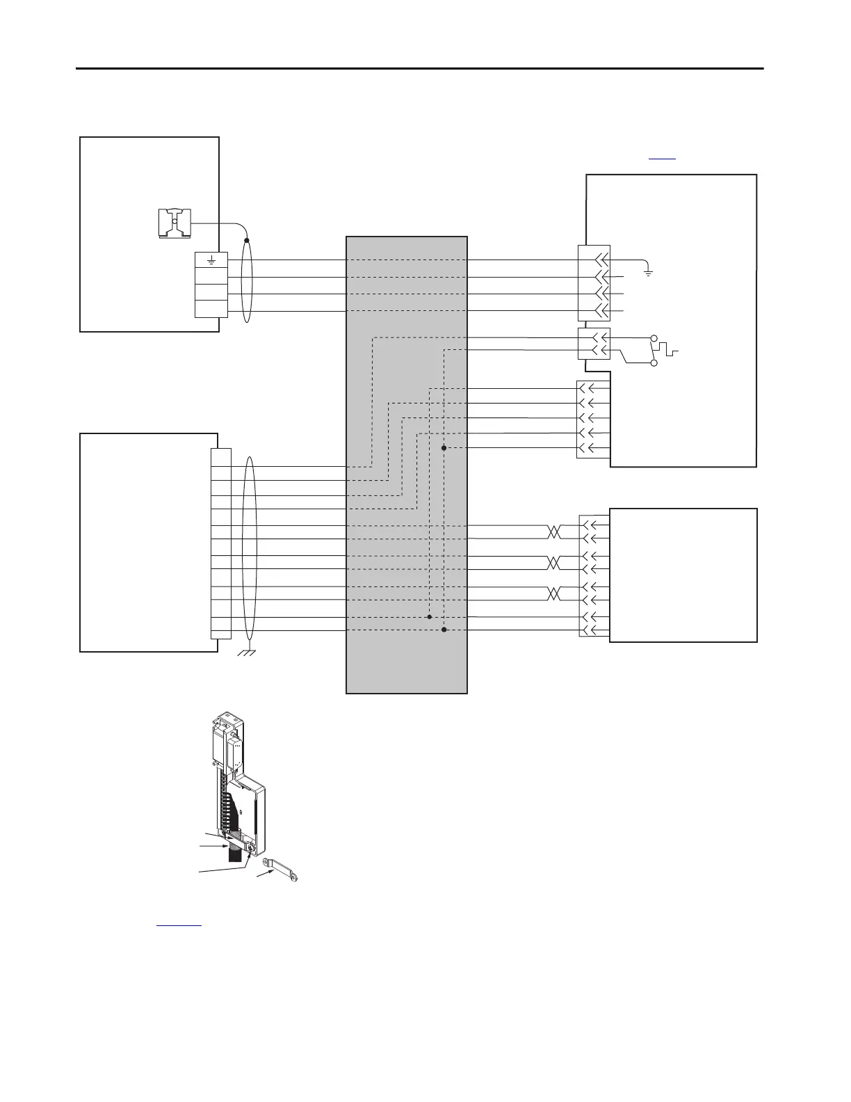
EasyManuals Logo
Home>Allen-Bradley>Servo Drives>2094-AC05-MP5

Allen-Bradley 2094-AC05-MP5 User Manual

Allen-Bradley 2094-AC05-MP5
290 pages
To Next Page IconTo Next Page
To Previous Page IconTo Previous Page
Page #211 background imageLoading...
Page #211 background image
Rockwell Automation Publication 2094-UM001J-EN-P - March 2017 211
Interconnect Diagrams Appendix A
Figure 108 - AM Module with LDC-Series or LDL-Series Linear Motors
(flying-lead cables)
W
V
U
GND
4
3
2
1
W
V
U
GREEN/YELLOW
BLACK
WHITE
RED
BLACK
BLACK
RED
WHITE
BLUE
ORANGE
BLACK
W
V
U
TS+
TS-
POWER
S1
S2
S3
COM
SIN+
SIN-
COS+
COS-
IM+
IM-
POWER
COM
TS+
S1
S2
S3
13
8
12
11
(AM+)
(AM-)
(BM+)
(BM-)
1
2
3
4
5
10
14
6
SIN+
SIN-
COS+
COS-
IM+
IM-
POWER
COM
(AM+)
(AM-)
(BM+)
(BM-)
Motor Power
(MP) Connector
Cable Shield
Clamp
Note 10
Note 15
LDC-Cxxxxxx-xHTx0 or
LDL-xxxxxxx-xHTx0
Linear Motor Coil with
Sin/Cos or TTL External Encoder
and Flying-lead Cables
Three-phase
Motor Power
Motor Feedback
(MF) Connector
Thermostat
Grounding Technique for
Feedback Cable Shield
Turn clamp over to hold
small cables secure.
Exposed shield secured
under clamp.
Clamp Screws (2)
Clamp
Refer to table on page 188
for note information.
IAM (inverter) or AM
Module
External
Sin/Cos or (TTL)
Encoder
Kinetix 6000
IAM or AM Module
Hall Effect
Module
Wire as shown using
cable type appropriate for
your application.
2090-K6CK-D15M
Low-profile Connector Kit
2090-K6CK-D15M
Connector Kit
Refer to Low Profile Connector Kit Installation Instructions,
publication 2094-IN007
, for connector kit specifications.

Table of Contents

Questions and Answers:

Question and Answer IconNeed help?

Do you have a question about the Allen-Bradley 2094-AC05-MP5 and is the answer not in the manual?

Allen-Bradley 2094-AC05-MP5 Specifications

General IconGeneral
BrandAllen-Bradley
Model2094-AC05-MP5
CategoryServo Drives
LanguageEnglish

Related product manuals