42 Rockwell Automation Publication 2094-UM001J-EN-P - March 2017
Chapter 2 Plan the Kinetix 6000 Drive System Installation
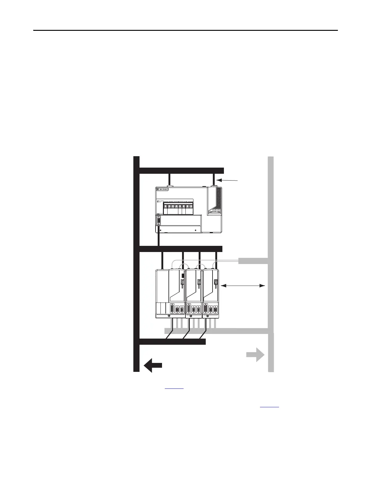
Observe these guidelines when the 2094-AL09 or 2094-BL02 LIM module is
used in the Bulletin 2094 system and mounted above the IAM module:
• The clean zone (C) is to the right and beneath the Bulletin 2094 system
(gray wireway).
• The dirty zone (D) is to the left and above the Bulletin 2094 system, and
above and below the LIM module (black wireway).
• The LIM VAC output is very dirty (VD). Use shielded cable with a
braid clamp attached at both ends of the cable to reduce the rating to
dirty (D).
• The Sercos fiber-optic cables are immune to electrical noise, but due to
their delicate nature, route them in the clean zone.
Figure 15 - Noise Zones (LIM mounted above IAM module)
(1) For examples of shield clamp attachment, refer to the System Design for Control of Electrical Noise Reference Manual,
publication GMC-RM001
.
(2) If drive system I/O cable contains (dirty) relay wires, route cable in dirty wireway.
(3) When space does not permit the 150 mm (6.0 in.) segregation, use a grounded steel shield instead. For examples, refer to the
System Design for Control of Electrical Noise Reference Manual, publication GMC-RM001
.
VD
D
D
D
D
C
C
C
Line Interface Module
Kinetix 6000
System
Dirty Wireway Clean Wireway
Motor Power Cables
Very dirty LIM/IAM
(1)
connections must be
shielded with braid
clamp at both ends.
I/O
(2)
and Feedback Cables
No sensitive
(3)
equipment within
150 mm (6.0 in.).
Route 24V DC I/O
shielded cable.
Route encoder/analog/registration
shielded cables.
Fiber-optic Cable
 Loading...


