Rockwell Automation Publication 2094-UM001J-EN-P - March 2017 53
Mount the Kinetix 6000 Drive System Chapter 3
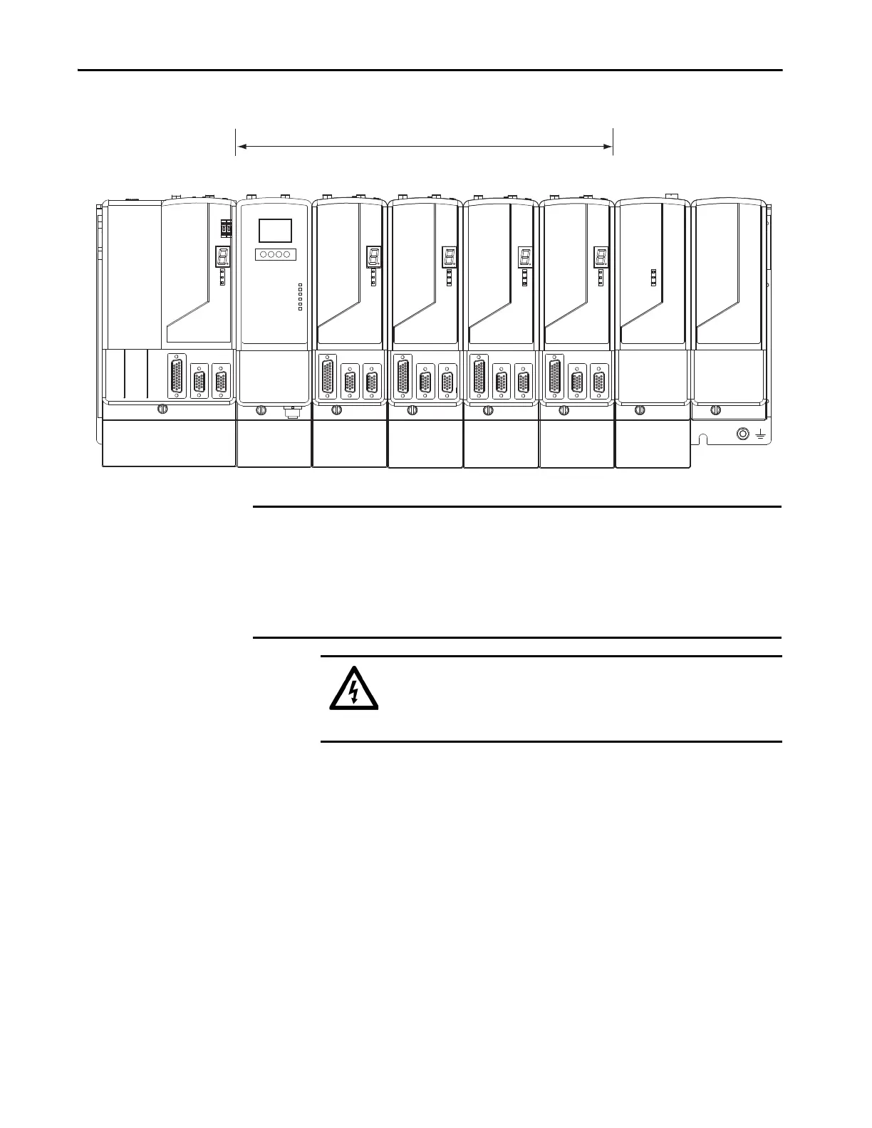
Figure 22 - Module Mounting Order Example
Highest Power Utilization
Lowest Power Utilization
Integrated Axis Module
2094-BC02-M02-x
IPIM Module
2094-SEPM-B24-S
Axis Module
2094-BM02-x
Axis Module
2094-BM02-x
Axis Module
2094-BM01-x
Axis Module
2094-BM01-x
Shunt Module
2094-BSP2
Slot-filler Module
2094-PRF
IMPORTANT The IAM module must be positioned in the leftmost slot of the power rail. Position your
AM/IPIM modules, shunt module, and slot-filler modules to the right of the IAM module.
The shunt module must be installed to the right of the last AM/IPIM module. Only slot-
filler modules can be installed to the right of the shunt module.
Do not mount the shunt module on power rails with a follower IAM module. Common-bus
follower IAM modules disable the internal, rail mounted, and external shunt modules.
SHOCK HAZARD: To avoid personal injury due to electrical shock, place a
2094-PRF slot-filler module in all empty slots on the power rail. Any power
rail connector without a module installed disables the Bulletin 2094 system;
however, control power is still present.
 Loading...


