Rockwell Automation Publication 2094-UM001J-EN-P - March 2017 63
Connector Data and Feature Descriptions Chapter 4
Kinetix 6000 drives do not support Heidenhain EnDat high-resolution
feedback; however, you can use the 2090-K6CK-KENDAT feedback module
to convert Heidenhain EnDat high-resolution feedback to Stegmann
Hiperface. Pin numbers in the table below refer to pins in the feedback
module.
Table 29 - Heidenhain EnDat
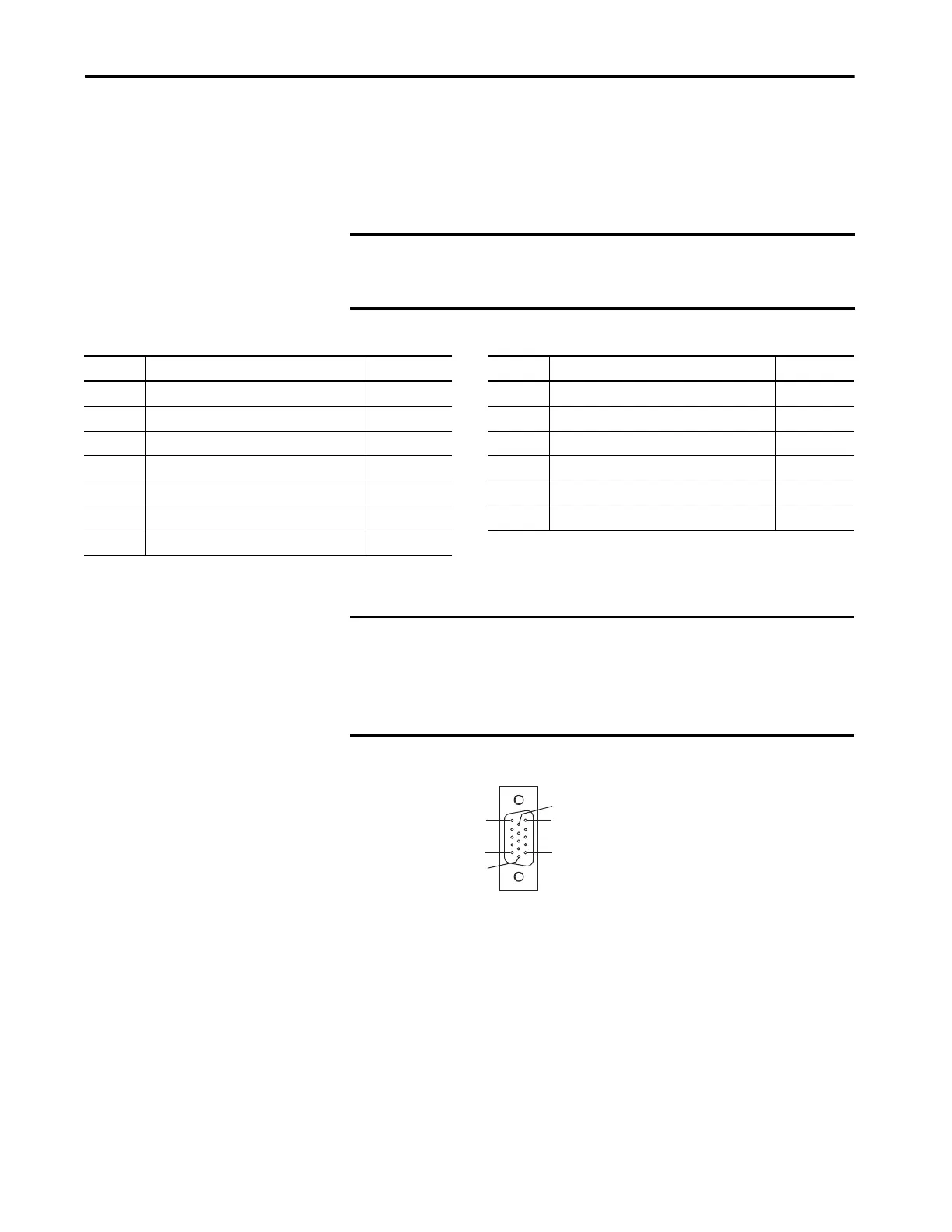
Figure 27 - Pin Orientation for 15-pin Motor Feedback (MF) Connector
IMPORTANT Only 2094-xCxx-Mxx-S and 2094-xMxx-S drives with firmware revision 1.116
or later support the use of 2090-K6CK-KENDAT feedback modules for
Heidenhain EnDat feedback.
Pin Description Signal Pin Description Signal
1 Sine differential input+ SIN+ 8 Serial data clock signal - CLK-
2 Sine differential input- SIN- 9 Serial data differential signal+ DATA+
3 Cosine differential input+ COS+ 10 Serial data differential signal - DATA-
4 Cosine differential input- COS- 11 Motor thermal switch+
(1)
TS+
5 Encoder power (+5V) EPWR_5V 12 Motor thermal switch-
(2)
TS-
6 Common ECOM 13 Reserved –
7 Serial data clock signal + CLK+
(1) Not applicable unless the motor has integrated thermal protection.
(2) When used with Allen-Bradley® motors and Bulletin 2090 cables, pin 12 is reserved.
IMPORTANT Combined motor-power cable length for all axes on the same DC bus must
not exceed 240 m (787 ft) with 460V systems or 160 m (525 ft) with 230V
systems. Drive-to-motor power cables must not exceed 90 m (295.5 ft).
System performance was tested at these cable length specifications. These
limitations also apply when meeting CE requirements.
Pin 11
Pin 6
Pin 15
Pin 1
Pin 10
Pin 5
 Loading...


