76 Rockwell Automation Publication 2094-UM001J-EN-P - March 2017
Chapter 4 Connector Data and Feature Descriptions
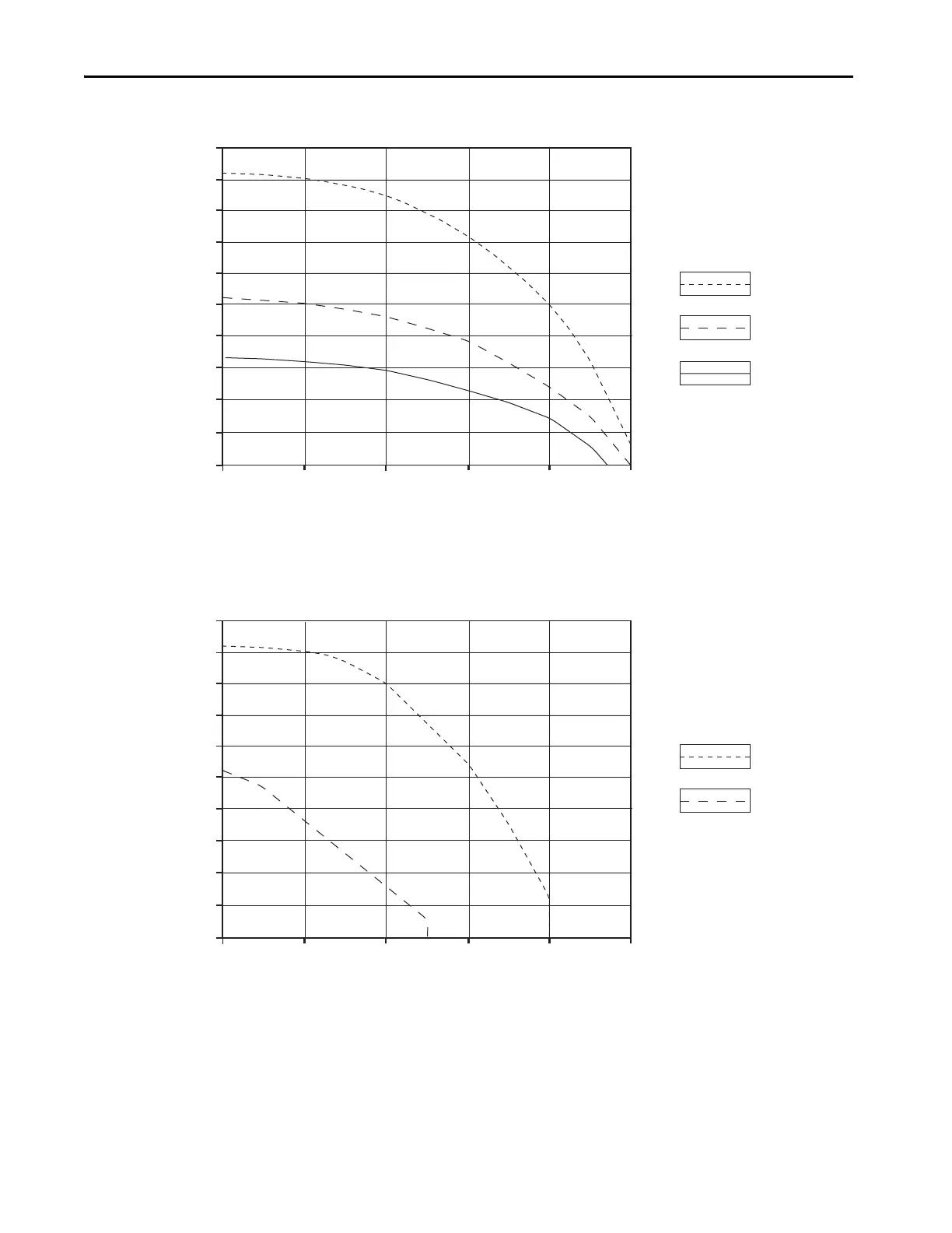
Figure 35 - Peak Inverter Overload (T
PK
< 2.0 s)
(1) Base current (I
Base
) and peak current (I
PK
) are a percentage of the continuous drive current rating (I
Cont
).
Figure 36 - Peak Inverter Overload (T
PK
< 2.0 s)
(1) Base current (I
Base
) and peak current (I
PK
) are a percentage of the continuous drive current rating (I
Cont
).
% Base Current (I /I )
0%
60%
100%
50%
45%
40%
35%
30%
25%
20%
15%
10%
5%
0%
80%20%
40%
I = 150%
I = 200%
I = 250%
Legend
Maximum Duty Cycle (D )
max
Cont
PK
PK
PK
(1)
Base
Applies to these Kinetix 6000 drives:
2094-BC01-MP5-S, 2094-BMP5-S,
2094-BC01-M01-S, 2094-BM01-S,
2094-BC02-M02-S, 2094-BM02-S,
2094-BC04-M03-S, 2094-BM03-S
% Base Current (I /I )
0%
60%
100%
50%
45%
40%
35%
30%
25%
20%
15%
10%
5%
0%
80%20%
40%
Legend
Maximum Duty Cycle (D )
max
Cont
PK
PK
(1)
Base
I = 150%
I = 200%
Applies to these Kinetix 6000 drives:
2094-BC07-M05-S, 2094-BM05-S
 Loading...


