86 Rockwell Automation Publication 2094-UM001J-EN-P - March 2017
Chapter 5 Connect the Kinetix 6000 Drive System
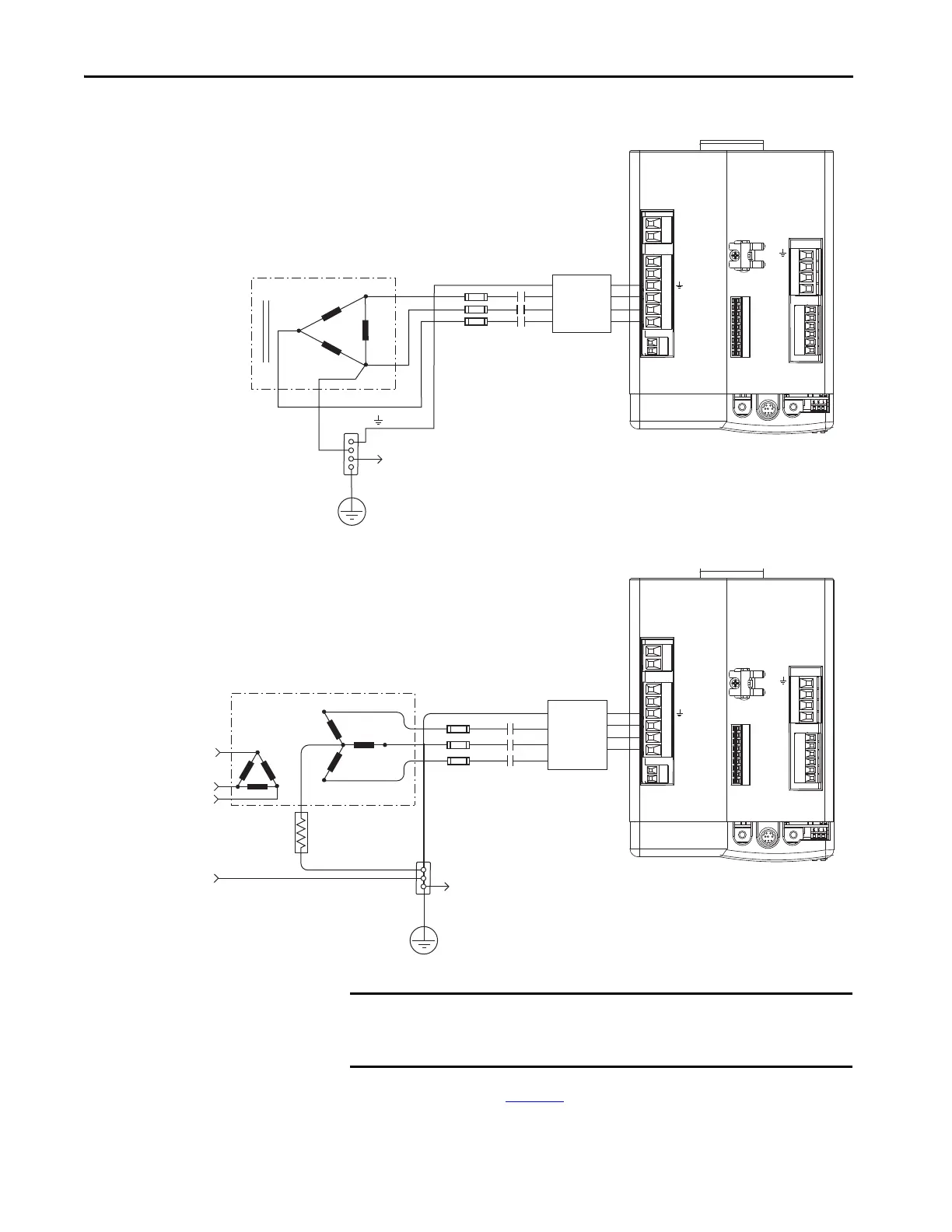
Figure 40 - Corner-grounded Power Configuration (Delta Secondary)
Figure 41 - Impedance-grounded Power Configuration (WYE Secondary)
Refer to Appendix A on page 187, for input-power interconnect diagrams with
and without the LIM module.
L3
L1
L2
DC-
DC+
L3
L2
L1
CONT EN-
CONT EN+
W
V
U
MBRK -
MBRK +
COM
PWR
DBRK -
DBRK +
CTRL 2
CTRL 1
1 2 3 4
1 2 3 4 5 6
1 2
1 2 3 4 5 6
1 2
BAUD
RATE
TX
RX
DPI
1 2 3 4 5 6 7 8 9
Transformer (Delta) Secondary
Bonded Cabinet
Ground
Transformer
Ground Grid or
Power Distribution Ground
Kinetix 6000 IAM Module,
Top View
Connect to power rail ground stud.
Three-phase
AC Line Filter
M1
Contactor
Circuit
Protection
L3
L2
L1
DC-
DC+
L3
L2
L1
CONT EN-
CONT EN+
W
V
U
MBRK -
MBRK +
COM
PWR
DBRK -
DBRK +
CTRL 2
CTRL 1
1 2 3 4
1 2 3 4 5 6
1 2
1 2 3 4 5 6
1 2
BAUD
RATE
TX
RX
DPI
1 2 3 4 5 6 7 8 9
Transformer
Three-phase
Input VAC
Phase Ground
Transformer (WYE) Secondary
Ground Grid or
Power Distribution Ground
Three-phase
AC Line Filter
Circuit
Protection
M1
Contactor
Bonded Cabinet Ground
Kinetix 6000 IAM Module,
Top View
Connect to power rail ground stud.
IMPORTANT Even though impedance-grounded and corner-grounded power
configurations have a ground connection, treat them as ungrounded when
installing Kinetix 6000 drive systems.
 Loading...


