Publication 1763-RM001B-EN-P - April 2007
Communications Instructions 375
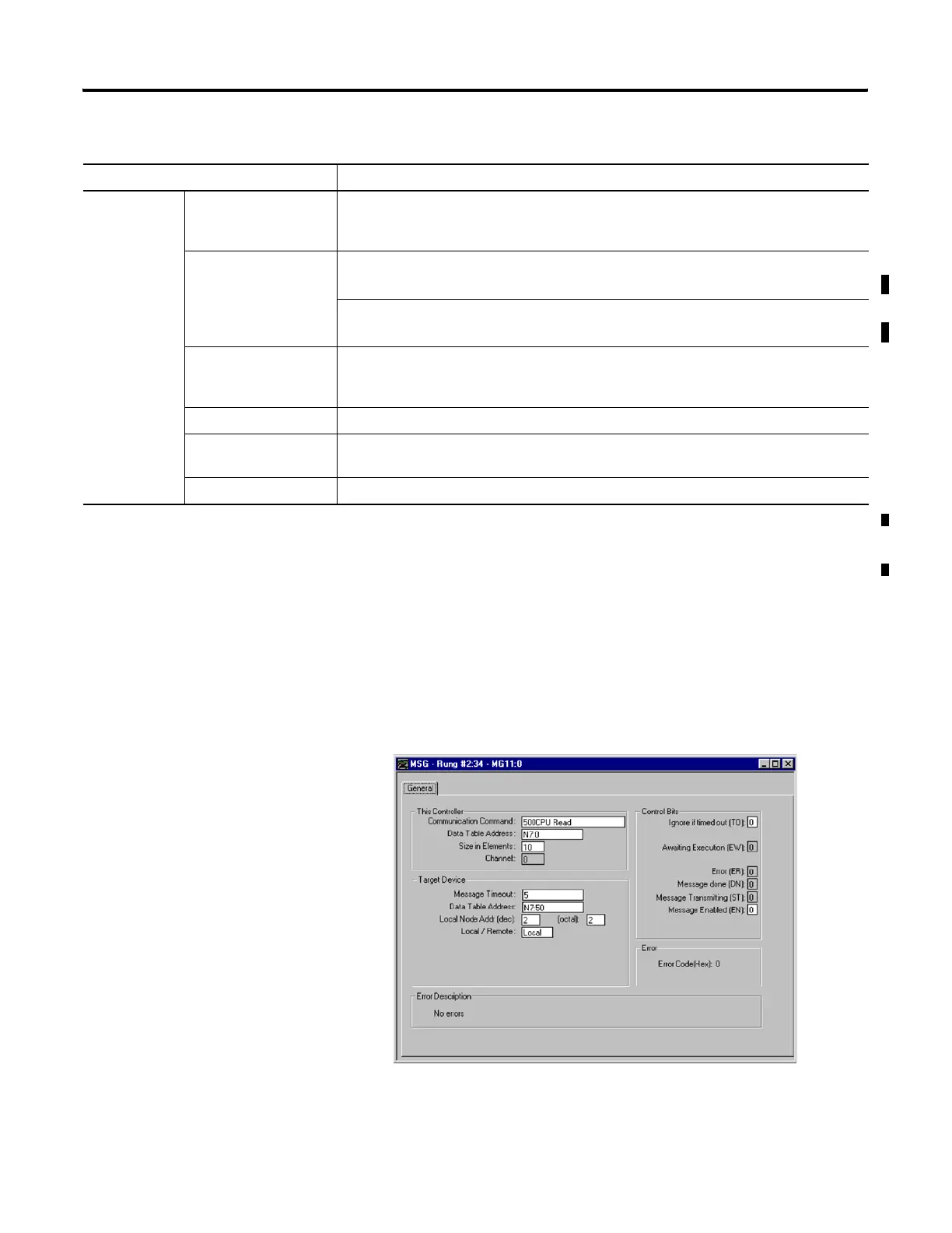
Example 1 - Local Read from a 500CPU
Message Instruction Setup
Target Device Message Timeout Defines the amount of time the controller waits for the reply before the message errors. A
timeout of 0 seconds means that the controller waits indefinitely for a reply. Valid range is
from 0 to 255 seconds.
Data Table Address
(500CPU and PLC5
message types)
For a Read, this is the address in the processor which is to return data.
Valid file types are S, B, T, C, R, N, L, and ST
(3)
.
For a Write, this is the address in the processor which receives data.
Valid file types are I, O, S, B, T, C, R, N, L, RTC
(1)
, and ST
(3)
.
Data Table Offset
(485CIF message types)
This is the word offset value in the common interface file (byte offset for PLC device) in the
target processor, which is to send the data.
MB Data Address Specifies the Modbus address in the target device. Valid range is from 1 to 65,536.
Local Slave Node
Address
Specifies the node number of the device that is receiving the message. Valid range is 0 to 31
for DH-485 protocol, 0 to 254 for DF1 protocol, 0 to 63 for DeviceNet, or 0 to 247 for Modbus.
Local/Remote Specifies whether the message is local or remote. (Modbus messages are local only.)
(1) MicroLogix 1100 OS Series A FRN3, 485CIF write ST-to-485CIF only.
(2) 500CPU write RTC-to-Integer or RTC-to-RTC only.
(3) MicroLogix 1100 Series B FRN 4 or later.
Parameter Description
efesotomasyon.com - Allen Bradley,Rockwell,plc,servo,drive

 Loading...


