Publication 1785-UM012D-EN-P - July 2005
Communicating with a PLC-5 Adapter Channel 7-17
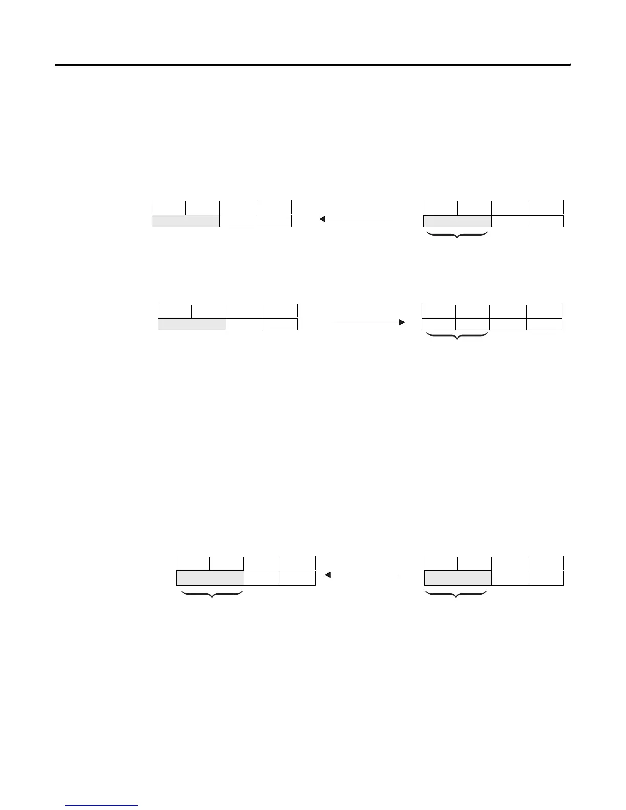
Do not program a block-transfer to group 0, module 1 since this area of the
discrete transfer configuration file is used for communication status exchanges
between the supervisory controller and the adapter-mode controller channel.
For example:
Monitoring the Status of the Adapter Channel
The supervisory controller receives status bits from the adapter-mode
controller in word 0 of the input image table for the rack that the
adapter-mode controller is emulating.
Adapter Channel’s Output Source File
Example Integer File
Scanner’s Input Image Table
0003040710131417
0003040708111215
Word
0
Status bits sent to scanner
0003040710131417 0003040708111215Word
0
Adapter Channel’s Input Destination File
Example Integer File
Scanner’s Output Image Table
xxx
module 1
module 1
Adapter Channel’s Output Source File
Example Integer File
Scanner’s Input Image Table
(Octal)
0003040710131417
0003040708111215Word
0
Status bits sent to scanner
Adapter channel statusStatus bits received
from adapter channel

 Loading...


