Publication 1785-UM012D-EN-P - July 2005
Preparing Fault Routines 15-7
Setting an Alarm
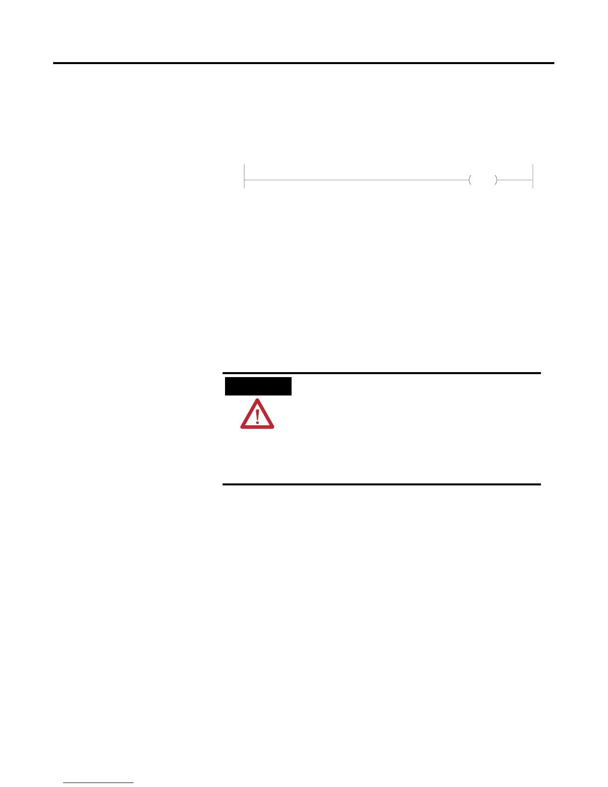
If you need an alarm to signal the occurrence of a major fault, put this rung
first in your fault routine program:
and combine it with a counter. You can also set an alarm in your fault routine
to signal when the fault routine clears a major fault.
Clearing a Major Fault
You can clear a major fault with one of these methods:
• Turn the keyswitch on the PLC-5 controller from REM to PROG to
RUN.
• Use the programming software to clear the major fault (if recoverable).
If you decide to clear the fault in the fault routine, follow these steps:
1. Place the ladder logic for clearing the fault at the beginning of the fault
routine.
2. Identify the possible major faults.
3. Select only those your application will let you safely clear. These are your
reference fault codes.
4. From the fault routine, examine the major fault code that the controller
stores in S:12.
5. Use an FSC instruction to compare the fault code to the reference file
that contains “acceptable” fault codes (word-to-file comparison).
output
alarm
ATTENTION
Clearing a major fault does not correct the cause of the
fault. Be sure to examine the fault bit and correct the
cause of the fault before clearing it.
For example, if a major fault is encountered causing bit
S:11/2 to be set, indicating a programming error, do
not use a fault routine to clear the fault until you
correct your program.

 Loading...


