Publication 1785-UM012D-EN-P - July 2005
Addressing I/O and Controller Memory 4-21
Specifying Symbolic Addresses
When you specify symbolic address, follow these guidelines:
• Start the name with an alphabetic character (not a number).
• The symbol must begin with a letter and can contain as many as 10 of
the following characters:
–
– A-Z (upper and lower case)
–
– 0-9
–
– underscore (_)
• You can substitute a symbolic address for word or bit addresses.
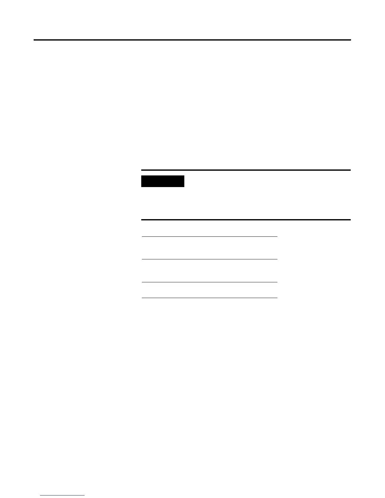
IMPORTANT
Symbols are a feature of the programming software (not
the controller) and are stored in a database on the hard disk
of the personal computer you are using. If you use a
terminal other than the one on which you defined the
symbols, you will not have access to the symbol database.
Example Logical Address Symbolic Address
Input image
(bit)
I:015/00
I:015/03
I:015/06
LS1
AUTO1
SW1
Output image
(bit)
O:013/00
O:013/02
O:013/04
M1
CL1
L1
Word F10:0
F10:1
Calc_1
Calc_2

 Loading...


