Publication 1785-UM012D-EN-P - July 2005
6-6 Communicating with Remote I/O
I/O Link Devices that Require 150Ω Termination Resistors
Configuring a Controller
Channel as a Scanner
Use this table to help you determine the controller channels you can configure
as a remote I/O scanner:
To configure a controller channel as a scanner, you:
• define an I/O status file, which stores information about the racks
connected to the controller, by using the controller configuration screen
in your programming software
• specify the scanner’s communication rate and diagnostic file and define a
scan list by using the scanner mode channel configuration screen in your
programming software
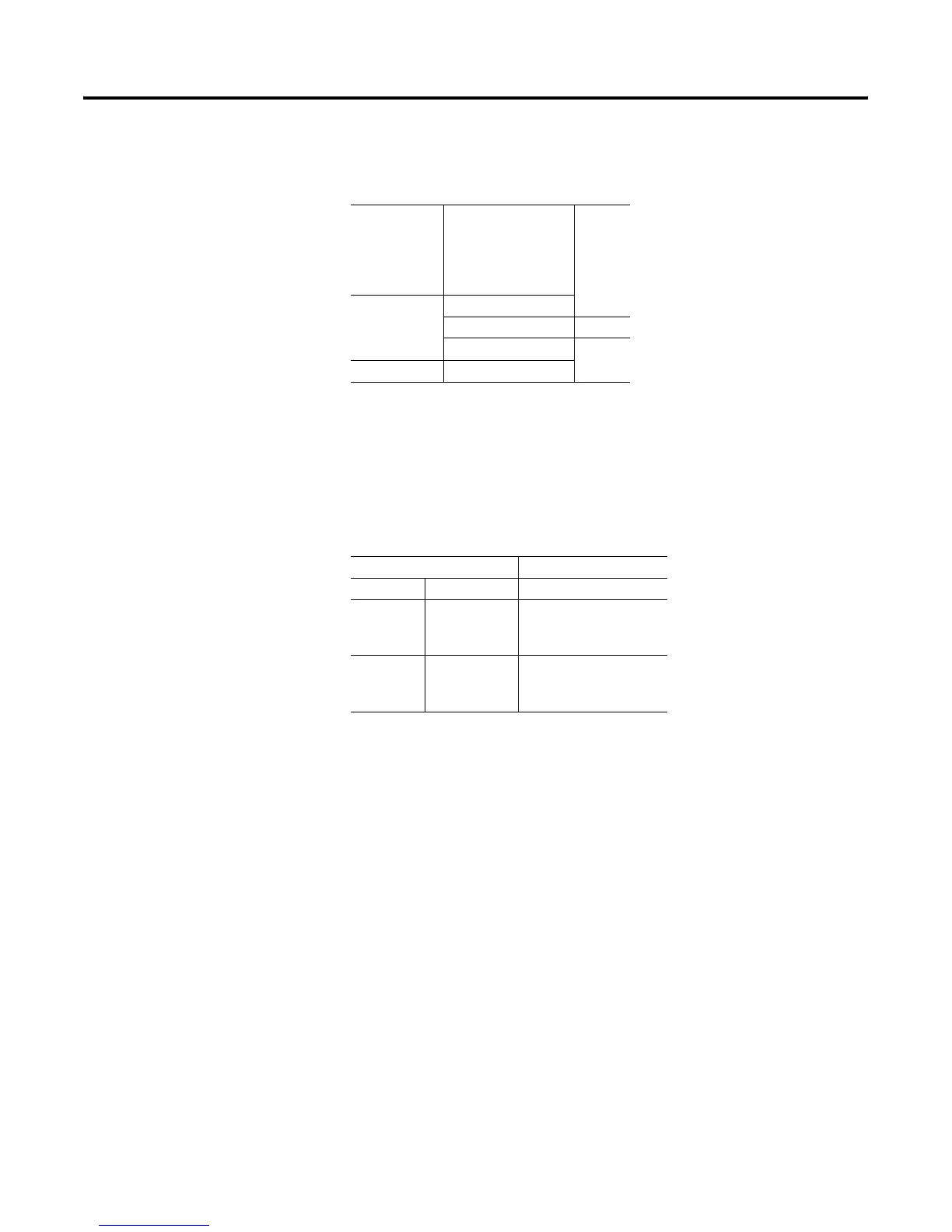
Device Type Catalog Number Series
Scanners 1771-SN
1772-SD, -SD2
1775-SR
1775-S4A, -S4B
6008-SQH1, -SQH2
All
Adapters 1771-AS
1771-ASB A
1771-DCM All
Miscellaneous 1771-AF
Controller
Channels that Support
Remote I/O Scanner
PLC-5/11 1A
PLC-5/20 PLC-5/20E 1B
PLC-5/30
PLC-5/40L
PLC-5/60L
PLC-5/40E
PLC-5/80E
1A, 1B
PLC-5/40
PLC-5/60
PLC-5/80
1A, 1B, 2A, 2B

 Loading...


