Publication 1785-UM012D-EN-P - July 2005
Addressing I/O and Controller Memory 4-3
Choosing an Addressing
Mode
For each I/O chassis in your system, you must define how many I/O chassis
slots make up an I/O group (1 word each in the input image table and output
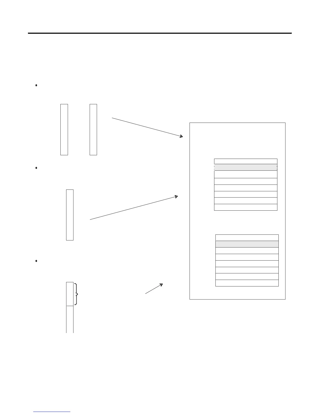
image table); this choice is the chassis’ addressing mode. Choose from among
these available modes:
When you place your I/O modules in the I/O chassis slots, the module’s
density determines how quickly I/O groups form. For example, let’s choose
1-slot addressing and see how 8-, 16-, and 32-point I/O modules fill controller
memory.
2-slot addressing
2 I/O chassis slots = 1 I/O group = 1 input image word and 1 output image
word = 16 input bits and 16 output bits.
1-slot addressing
1 I/O chassis slot = 1 I/O group = 1 input image word and 1 output image
word = 16 input bits and 16 output bits.
1/2-slot addressing
1/2 of an I/O chassis slot = 1 I/O group = 1 input image word and 1 output image
word = 16 input bits and 16 output bits.
x
x
x
x
x
x
x
x
Output Image Table
Word #
Input Image Table
Word #
16 bits input 16 bits output
16 bits input and 16 bits output
16 bits input and 16 bits output
Controller memory
Rack x
x
x
x
x
x
x
x
x

 Loading...


