Publication 1785-UM012D-EN-P - July 2005
4-2 Addressing I/O and Controller Memory
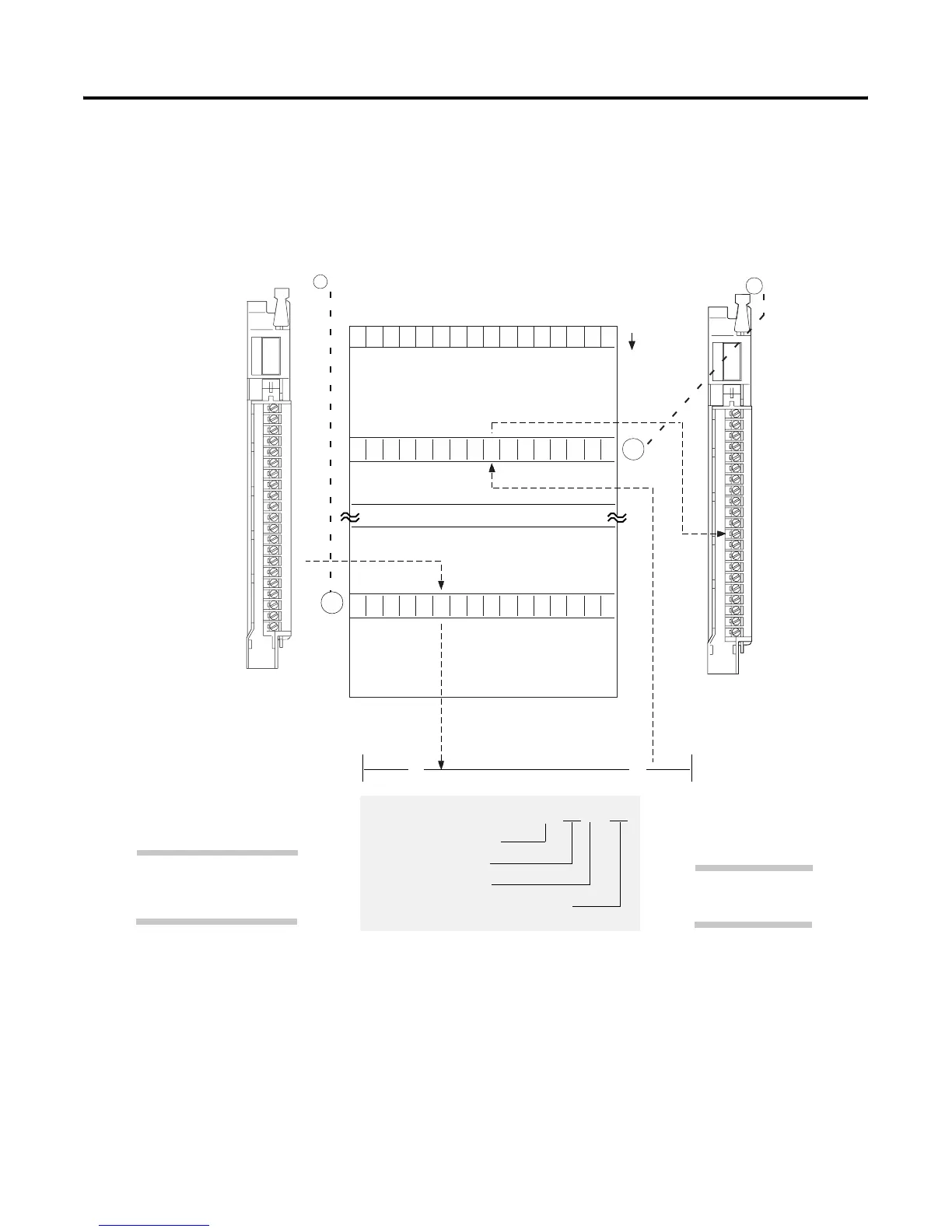
The figure below shows the relationship between an I/O terminal and its
location in controller memory.
I/O Addressing as It Relates to an I/O Terminal
Now that you are familiar with how controller memory is segmented to
address a specific I/O terminal, the next section explains available addressing
modes. These modes let you define the relationship between an I/O chassis
slot and an I/O group (16 input bits and 16 output bits).
17 16 15 14 13 12 11 10 07 06 05 04 03 02 01 00
Input Module
(1771-IAD)
A
B
C
D
00
01
02
03
04
05
06
07
10
11
12
13
14
15
16
17
E
Output Module
(1771-OAD)
A
B
C
D
00
01
02
03
04
05
06
07
10
11
12
13
14
15
16
E
17
| | ( )
I:014
12
O:015
07
Input Image Table
Output Image Table
I:014/12
I for input or O for output
2-digit I/O rack number
I/O group number (0-7)
input or output number (0-7,10-17) (bit)
00
05
07
00
04
07
word
address
rack number 01
I/O group number 5
rack number 01
I/O group number 4
17 16 15 14 13 12 11 10 07 06 05 04 03 02 01 00
17 16 15 14 13 12 11 10 07 06 05 04 03 02 01 00
04
I/O image table is
addressed octally.
Notice how input and output
image file addresses
correspond to hardware.

 Loading...


