Publication 1785-UM012D-EN-P - July 2005
Communicating with Remote I/O 6-17
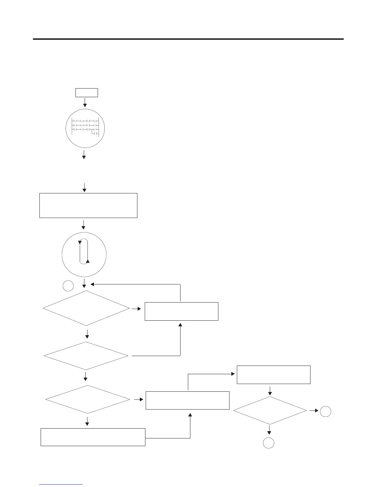
Block-Transfer Sequence
with Status Bits
The following figure describes the different states of the block-transfer
status bits.
bit and starts the watchdog timer.
I/O scanner
ladder logic
The processor sends the block-transfer
request to the I/O scanner, sets the .EW bit,
and resumes the program scan.
Transfers the block-transfer
request to/from the I/O chassis.
Start
Detects that a rung containing a
block-transfer is enabled and sets the
enable .EN bit and resets the .ST, .DN, .ER,
and .EW status bits.
Does the module respond?
yes
B
no
C
see page
6-19
The scanner accesses the BTW file in the data
table and copies the data to the active buffer.
Is an active buffer available?
Executes block-transfer
asynchronously to the
program scan
Does this slot address
have a BT in process?
no
yes
The scanner place the request
in the waiting queue.
A
Is the request a BTW?
yes
no
yes
no
see page 6-18
The scanner sets the .ST status

 Loading...


