EasyManuals Logo

Allen-Bradley PLC-5 User Manual

Allen-Bradley PLC-5
388 pages
To Next Page IconTo Next Page
To Previous Page IconTo Previous Page
Page #243 background imageLoading...
Page #243 background image
Publication 1785-UM012D-EN-P - July 2005
Preparing Fault Routines 15-5
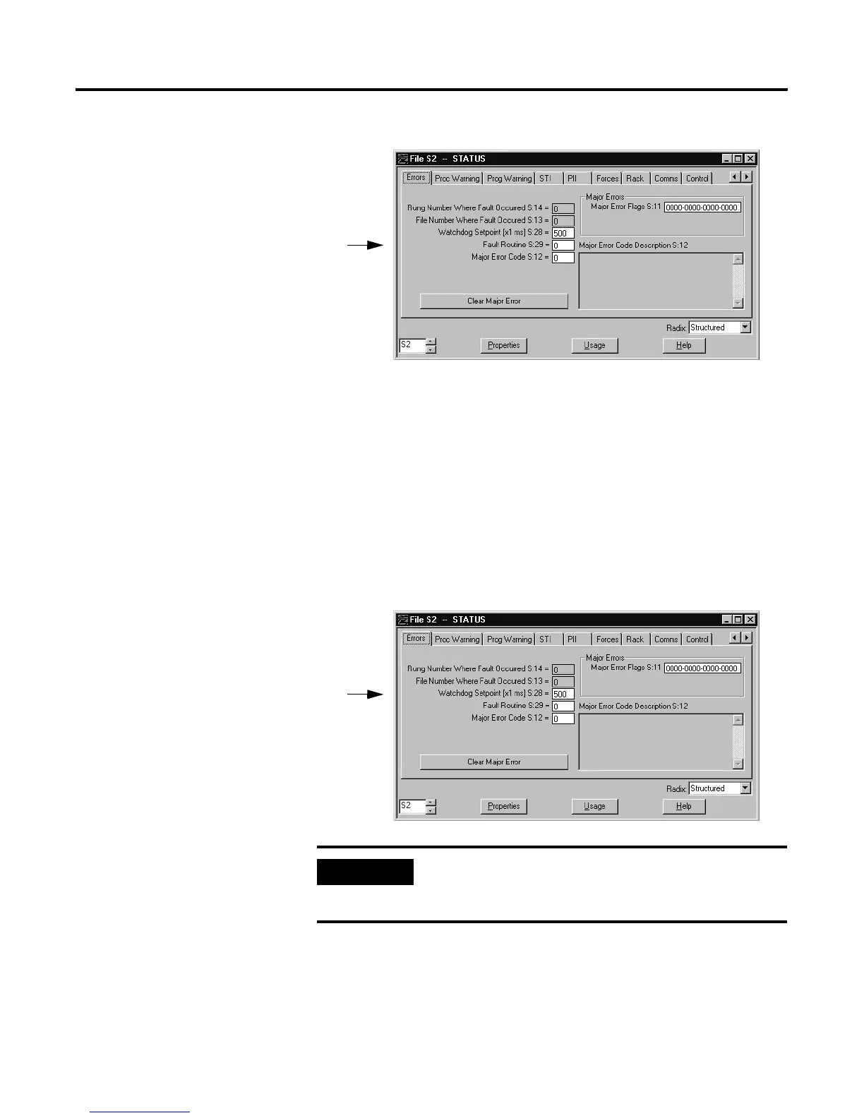
To define a controller fault routine:
For more information about fault codes, see the documentation for your
programming software.
Defining a Watchdog Timer
The watchdog timer (S:28) monitors the program scan. If the scan takes
longer than the watchdog timer value, a fault routine is initiated and executed.
The timer is the maximum time (in ms) for the watchdog; or if you use an SFC,
it is the maximum time for a single pass through all the active steps.
To define a different value other than the default: .
IMPORTANT
The watchdog timer can go only as low as 10 ms,
even though the programming software allows
single-digit inputs

Table of Contents

Other manuals for Allen-Bradley PLC-5

Questions and Answers:

Question and Answer IconNeed help?

Do you have a question about the Allen-Bradley PLC-5 and is the answer not in the manual?

Allen-Bradley PLC-5 Specifications

General IconGeneral
Programming SoftwareRSLogix 5
Programming LanguagesLadder Logic
Power Supply120/240V AC or 24V DC
Communication PortsDH+, Remote I/O, Ethernet/IP, ControlNet
Operating Temperature0 to 60°C (32 to 140°F)
Relative Humidity5 to 95% non-condensing
MemoryUp to 64K words (user program and data)

Related product manuals