Publication 1785-UM012D-EN-P - July 2005
1-8 Understanding Your Programmable Controller
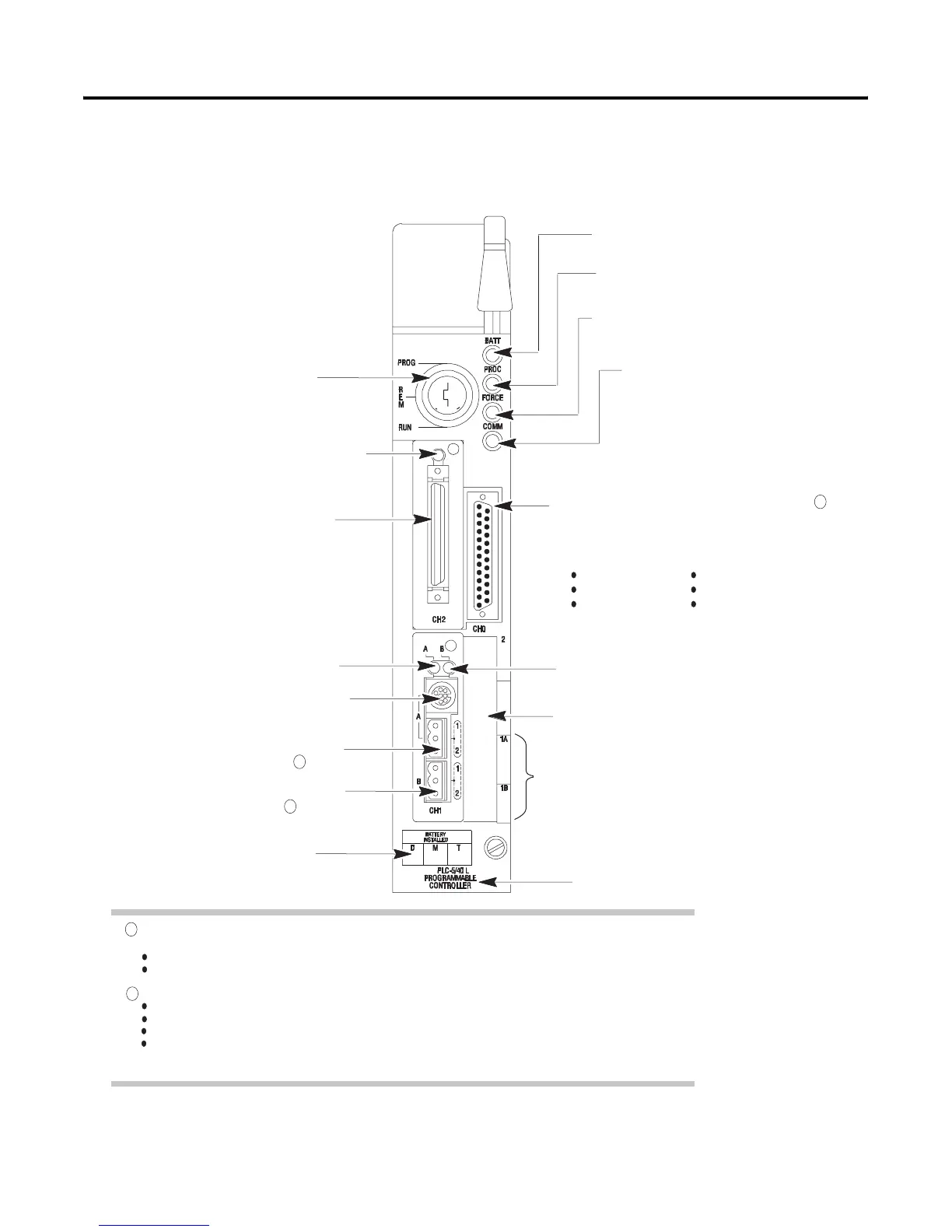
PLC-5/40L and -5/60L Controller Front Panels
Channel 0 is optically-coupled (provides high electrical noise immunity) and can be used with most RS-422A
equipment as long as:
termination resistors are not used
the distance and transmission rate are reduced to comply with RS-423 requirements
Configure these 3-pin ports for:
remote I/O scanner,
remote I/O adapter,
DH+ communication
unused
channel 1B communication port; its default
configuration is remote I/O scanner
Use this port with ASCII or DF1 full-duplex, half-duplex
master, and half-duplex slave protocols. The port's
default configuration supports controler programming:
channel 0*25-pin D-shell serial port; supports standard
EIA RS-232C and RS-423 and is RS-422A compatible
one stop-bit
BCC error check
no handshaking
DF1 point-to-point
2400 bps
no parity
battery indicator (red when the battery is low)
controller RUN/FAULT indicator (green when
running; red when faulted)
force indicator (amber when I/O forces
are enabled)
channel 0 communication status indicator
(green when the channel is communicating)
Install memory module here
Use these labels to write information about the
channel: communication mode, station addresses etc.
Install battery here
channel 1B status indicator (lights green and red)
PLC-5 family member designation
keyswitch; selects controller mode
channel 1A communication port; its default
configuration is DH+ communication
8-pin mini-DIN, DH+ programming terminal
connection parallel to channel 1A
channel 2 communication port; a 50-pin,
dedicated extended-local I/O port
channel 1A status indicator
(lights green and red)
channel 2 extended-local I/O status indicator
(green when functioning normally; red when
not functioning)
2
1
2
2
1

 Loading...


