Publication 1785-UM012D-EN-P - July 2005
4-4 Addressing I/O and Controller Memory
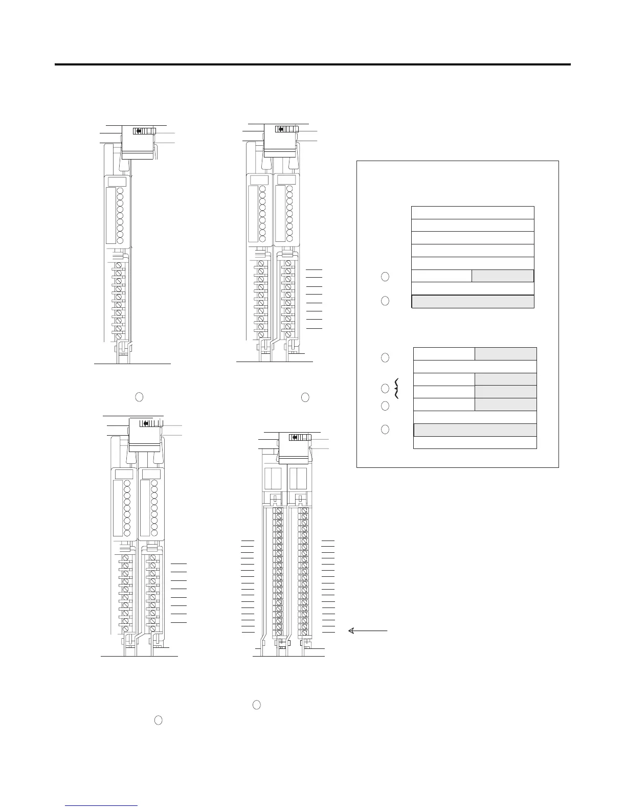
18-and 16-point Example
1-slot addressing (1 I/O chassis slot = 1 I/O group = 1 input image
word and 1 output image word = 16 input bits and 16 output bits.)
0
1
2
3
4
5
6
7
Output Image Table
Word #
0
1
2
3
4
5
6
7
Input Image Table
Word #
Controller memory
Rack x
0017 bits
0017 bits
00
01
02
03
04
05
06
07
10
11
12
13
14
15
16
17
Input
Terminals
Input
Termi
nals
An 8-point I/O module occupies
8 bits in a word. See
00
01
02
03
04
05
06
07
Input
Terminals
Input
Terminals
Two 8-point input modules occupy 8
bits of each group. See
00
01
02
03
04
05
06
07
Input
Terminals
Output
Terminals
An 8-point input module in group 4
occupies the first eight bits of input
word 4. The 8 point output module
occupies the first 8-output bits in
output word 5. See
Group 2 Group 3
Group 4 Group 5 Group 6 Group 7
16-point I/O modules occupy 16 bits,
an entire word, in the image table.
See
Group 0
00
01
02
03
04
05
06
07
10
11
12
13
14
15
16
17
00
01
02
03
04
05
06
07
10
11
12
13
14
15
16
17
Input
Terminals
Output
Terminals
If you were to address the device attached to
this output circuit in your control program, the
address would be O:xx7/17.
00
01
02
03
04
05
06
07
00
01
02
03
04
05
06
07
0 1
2 3
4 5
6 7
2
1
3
4
3
4
2
1
3
4

 Loading...


