Publication 1785-UM012D-EN-P - July 2005
Addressing I/O and Controller Memory 4-5
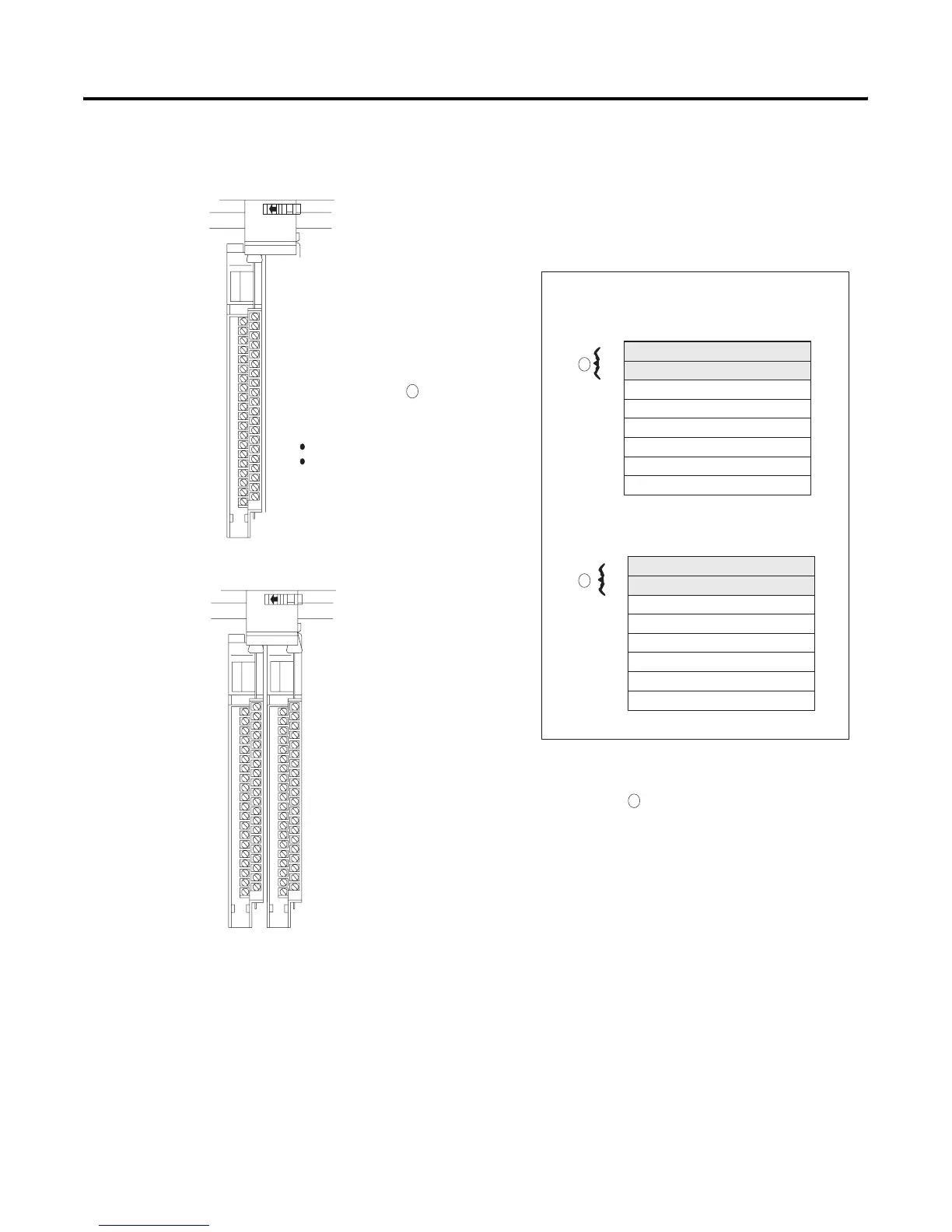
32-point Example
1-slot addressing (1 I/O chassis slot = 1 I/O group = 1 input image
word and 1 output image word = 16 input bits and 16 output bits.)
0
1
2
3
4
5
6
7
Output Image Table
Word #
0
1
2
3
4
5
6
7
Input Image Table
Word #
Controller memory
Rack x
0017 bits
0017 bits
Group 0 Group 1
32-point output module
32-point input module
32-point I/O modules use the entire word
of their group and borrow the entire word
of the next group. See .
Since the module is in group 0 and the
inputs for group 0 and group 1 are used,
you must:
install an output module in group 1
or leave the slot empty
Group 0
32-point input module
Since the input image table for group 1 is unavailable because it is
being used by the input module of group 0, installing a 32-point output
module makes use of output image table of group 0 and 1. See .
You can also install 8- or 16-point output modules. But you cannot
install another input module since all the input image space for groups
0 and 1 are used by the input module of group 0.
0 1
0 1
2
1
2
1

 Loading...


