Publication 1785-UM012D-EN-P - July 2005
6-26 Communicating with Remote I/O
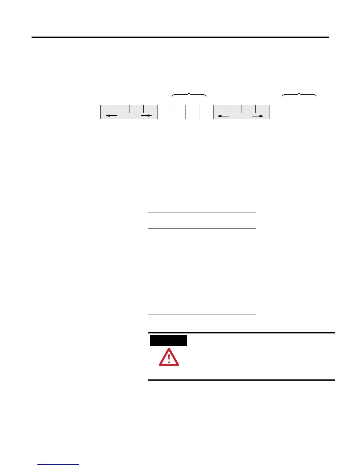
Bit Layout Diagrams for the Second Word Allotted to a Remote I/O Rack or an
Extended Local I/O Rack
00010203040506070809101112131415
Not Used
Not Used
Inhibit Bits
Reset Bits
N15:15
This Bit: Corresponds to:
Inhibit Bits
00 first 1/4 rack
starting I/O group 0
01 second 1/4 rack
starting I/O group 2
02 third 1/4 rack
starting I/O group 4
03 fourth1/4 rack
starting I/O group 6
Reset Bits
08 first 1/4 rack
starting I/O group 0
09 second 1/4 rack
starting I/O group 2
10 third 1/4 rack
starting I/O group 4
11 fourth1/4 rack
starting I/O group 6
ATTENTION
When you use a ladder program or the software to
inhibit and reset an I/O rack, you must set or clear the
reset and inhibit bits that correspond to each quarter
rack in a given chassis. Failure to set all the appropriate
bits could cause unpredictable operation due to
scanning only part of the I/O chassis.

 Loading...


