Rockwell Automation Publication 1783-UM003G-EN-P - December 2012 149
Appendix
A
I/O Data Types
Pre-defined RSLogix 5000 tags for Input and Output data types have a structure
corresponding to the switch (module) selected when it was added to the I/O tree.
Its members are named in accordance with the port names.For example, if a user
selects the 18-port switch, the 18 port names corresponding to that module are
visible. The other member names (19…26) are hidden.
You can disable a switch port by setting the corresponding bit in the output tag.
The output bits will be applied every time the switch receives the output data
from the controller when the controller is in Run mode. When the controller is in
Program mode, the output bits are not applied.
The port is enabled if the corresponding output bit is 0. If you enable or disable a
port by using the Device Manager Web interface or the CLI, the port setting may
be overridden by the output bits the next time they are applied. The output bits
will always take precedence, regardless of whether the Device Manager Web
interface or CLI was used to enable or disable the port.
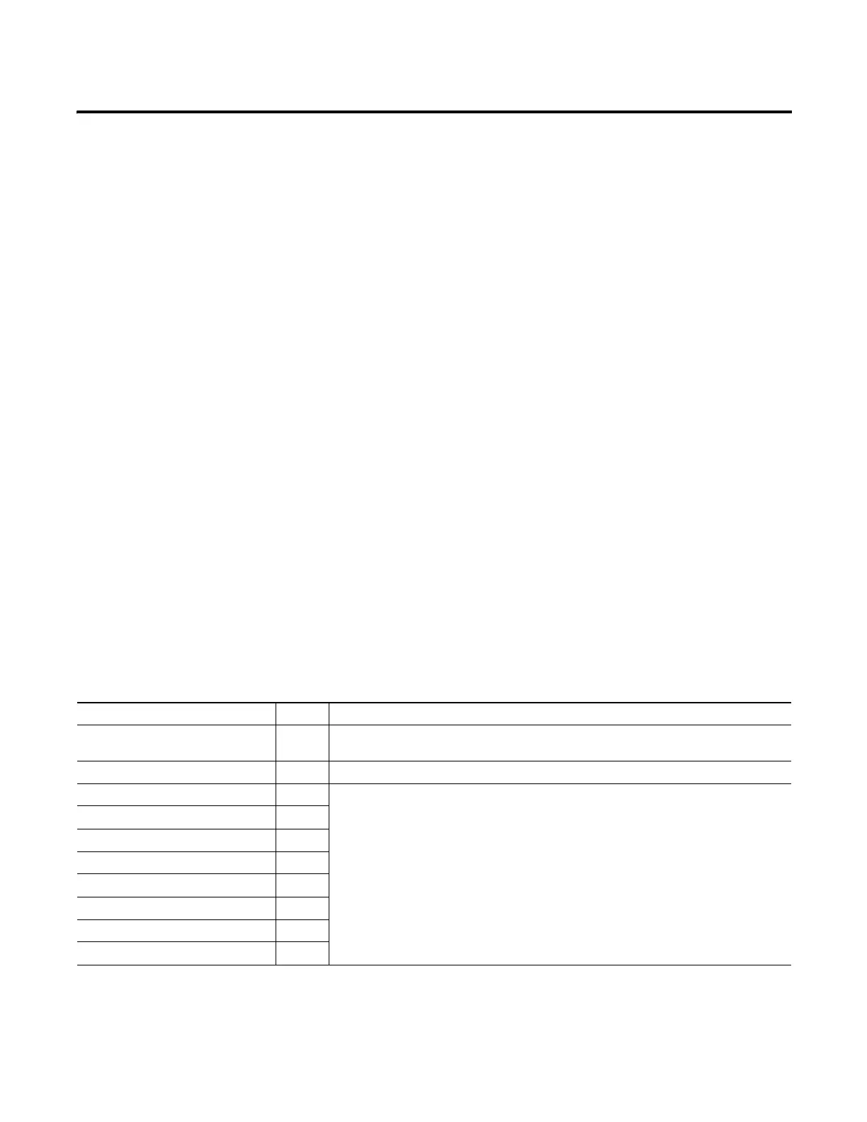
The following tables show input and output data types for all 26 ports of the
switch, as well as port assignments for data types.
Input Data Types
Tag Name Type Description
I:Fault DINT If there is s communication fault between the controller and the switch all 32 bits in the module
fault word are set to 1
I:AnyPortConnected BOOL Indicates that at least one port has a link status or active
I:PortGi1_1Connected BOOL Indicates that a particular port has link status active
0 = Link not active
1 = Link active
I:PortGi1_2Connected BOOL
I:PortFa1_1Connected BOOL
I:PortFa1_2Connected BOOL
I:PortFa1_3Connected BOOL
I:PortFa1_4Connected BOOL
I:PortFa1_5Connected BOOL
I:PortFa1_6Connected BOOL
 Loading...


