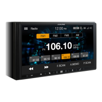
ALPINE iLX-F509E 68-41657Z84-A (EN)ALPINE iLX-F509E 68-41657Z84-A (EN)
63-EN
Installation and Connections
DO NOT USE BOLTS OR NUTS IN THE BRAKE OR
STEERING SYSTEMS TO MAKE GROUND C
Bolts or nuts used for the brake or steering syst
other safety-related system), or tanks should NE
for installations or ground connections. U
could disable control of the vehicle and cause fir
DO NOT INSTALL IN LOCATIONS
VEHICLE OPERATION, SUCH AS THE STEERING
OR SHIFT LEVER.
Doing so may obstruct forwar
etc. and results in serious accident.
DO NOT INSTALL THE MONITOR NEAR THE P
SEAT AIR BAG.
If the unit is not installed correctly the air bag ma
function correctly and when trigger
cause the monitor to spring upwar
and injuries.
CAUTION
HAVE THE WIRING AND INSTALLA
EXPERTS.
The wiring and installation of this unit requir
technical skill and experience. To ensure safety
contact the dealer where you purchased this pr
have the work done.
USE SPECIFIED ACCESSORY PARTS AND INST
SECURELY.
Be sure to use only the specified accessory parts
other than designated parts ma
internally or may not secur
may cause parts to become loose r
product failure.
ARRANGE THE WIRING SO IT IS NO
PINCHED BY A SHARP METAL EDGE.
Route the cables and wiring away from mo
the seat rails) or sharp or pointed edges. T
crimping and damage to the wiring. If wir
through a hole in metal, use a rubber grommet t
the wire’s insulation from being cut b
the hole.
DO NOT INSTALL IN LOCATIONS
OR DUST.
Avoid installing the unit in loca
moisture or dust. Moisture or dust that penetrat
unit may result in product failure.
Precautions
• Be sure to disconnect the cable from the (–) battery post
before installing your unit. This will reduce any chance of
damage to the unit in case of a short-circuit.
• Be sure to connect the color coded leads according to the
diagram. Incorrect connections may cause the unit to
malfunction or damage to the vehicle’s electrical system.
• When making connections to the vehicle’s electrical
system, be aware of the factory installed components (e.g.
on-board computer). Do not tap into these leads to
provide power for this unit. When connecting the unit to
the fuse box, make sure the fuse for the intended circuit
of the unit has the appropriate amperage. When in doubt,
consult your Alpine dealer.
• The unit uses female RCA-type jacks for connection to
other units (e.g. amplifier) having RCA connectors. You
may need an adaptor to connect other units. If so, please
contact your authorized Alpine dealer for assistance.
• Be sure to connect the speaker (–) leads to the speaker (–)
terminal. Never connect left and right channel speaker
cables to each other or to the vehicle body.
Accessory List
■
iLX-507E
Main unit ................................................................................................. 1
Quick Reference Guide .................................................................1set
<Cables>
Power cable ............................................................................................ 1
GPS Antenna .......................................................................................... 1
Antenna mounting plate ................................................................... 1
Cable clamp for antenna .............................................................1set
USB extension cable ............................................................................1
PRE OUT cable ....................................................................................... 1
Microphone ............................................................................................1
CAMERA cable ....................................................................................... 1
REMOTE cable ........................................................................................ 1
Camera input adapter.........................................................................2
<Main unit mounting parts>
Face Plate.................................................................................................1
HDMI Bracket ......................................................................................... 1
Flush head screw (M5×8) ...................................................................4
Screw (M5×8) ......................................................................................... 4
■
iLX-F509E/iLX-F511E
Main unit ................................................................................................. 1
Display unit .............................................................................................1
Quick Reference Guide .................................................................1set
<Cables>
Power cable ............................................................................................ 1
GPS Antenna .......................................................................................... 1
Antenna mounting plate ................................................................... 1
Cable clamp for antenna .............................................................1set
PRE OUT cable ....................................................................................... 1
Microphone ............................................................................................1
CAMERA cable ....................................................................................... 1
REMOTE cable ........................................................................................ 1
Camera input adapter.........................................................................2
<Main unit mounting parts>
HDMI Bracket ......................................................................................... 1
Flush head screw (M5×8) ...................................................................4
Screw (M5×8) ......................................................................................... 4
<Display unit mounting parts>
Cover Rear ............................................................................................... 1
Cover Hinge ............................................................................................1
Power Plate ............................................................................................. 1
Sheet Rear ............................................................................................... 1
– 2×50 mm ......................................................................................... 2
– 2×35 mm ......................................................................................... 2
– 2×20 mm ......................................................................................... 4
Sheet Hinge ............................................................................................ 1
Sheet cap .................................................................................................1
Screw (M5×8) ......................................................................................... 4
Screw (M3×4) ......................................................................................... 2
Screw Bind (M2.6×6) ...........................................................................2
Installation
Mounting (iLX-F509E/iLX-F511E only)
Consult “Position Adjustment and Mounting
Dimensions of the Display” (page 65) in advance so
that this unit does not obstruct your field of vision or
impair driving when mounted.
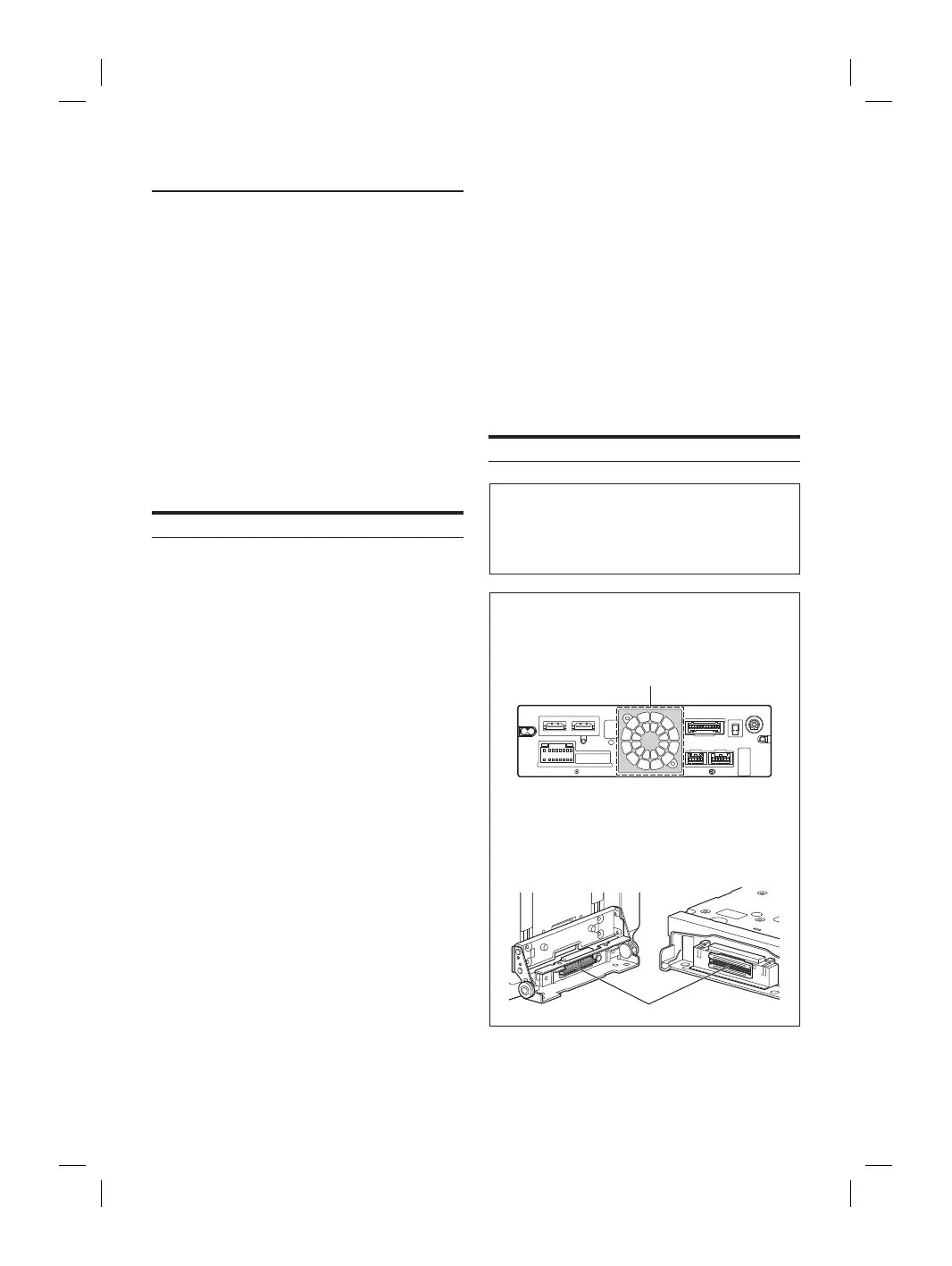
Caution
• Do not block the unit’s fan, thus preventing air
circulation. If blocked, heat will accumulate inside the
unit and may cause a fire.
Air ventilation hole
Rear of the Unit
• When installing the display unit and main unit, do not
touch the connectors with your hands. (iLX-F509E/
iLX-F511E only)
<Display unit> <Main unit>
Connectors