ALPINE iLX-F509E 68-41657Z84-A (EN)ALPINE iLX-F509E 68-41657Z84-A (EN)
67-EN
Installation example using the
Original Mounting Bracket
1 Mount the original mounting brack
unit using the supplied screws.
• If you do not have the original mounting br
mount the Double din KIT* (pro
mounting bracket), etc. to the main unit.
* Sold separately.
■
iLX-507E
Original Mounting
Bracket
Screws (M5×8)
(included)
Face plate (Included)
■
iLX-F509E/iLX-F511E
Original Mounting
Bracket
Screw
2 Connect all other leads of the unit ac
to details described in the “Connec
(page 69).
3 Mount the unit in a car.
• Fix the cables carefully. D
o
no
t
da
m
ag
e
th
e
m
by
mounting them into movable parts
rail, or by locating them against shar
edges.
4 Reattach the removed vehicle par
etc.) or other aftermarket dash k
the vehicle.
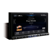
Adjust the up-down position of the
Display unit (iLX-F509E/iLX-F511E)
Adjust the up-down position of the display according to the
mounting position on the vehicle before mounting the
display unit.
Default setting: 0 mm
1 Remove the 4 screws on the rear of the
display unit, then adjust the up-down
position.
Screws (M2.6× 8)
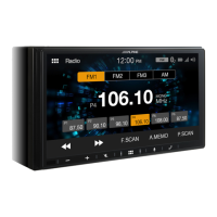
2 Attach the Sheet Rear in a position that aligns
with the up-down position of the display unit.
Sheet Rear
(Included)
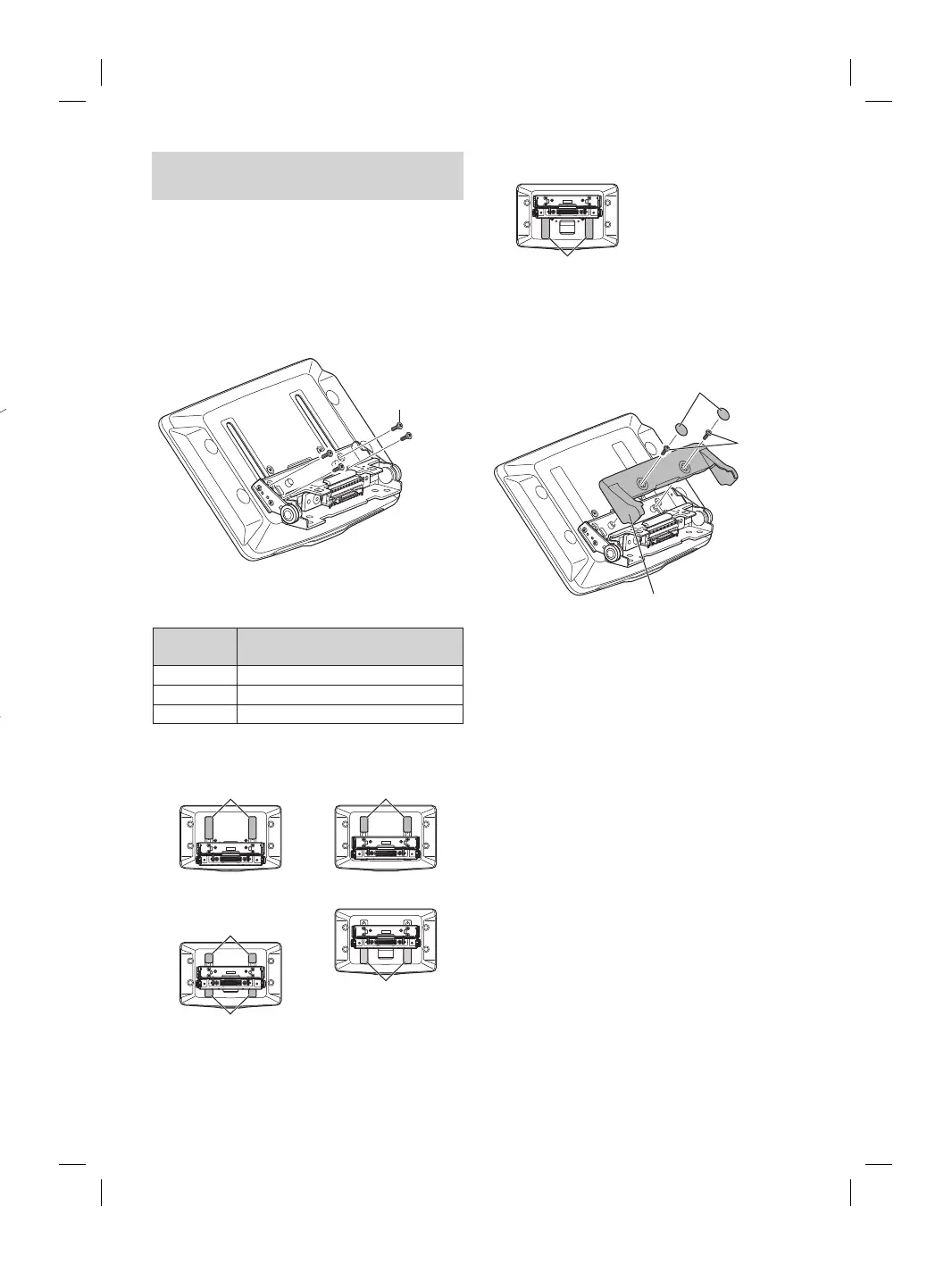
up-down position
2×50 mm: for up-down position 0 mm or -60 mm
2×35 mm: for up-down position -15 mm or -45 mm
2×20 mm: for up-down position -30 mm
0 mm
Sheet Rear
(2×50 mm)
-15 mm
Sheet Rear
(2×35 mm)
-30 mm
Sheet Rear
(2×20 mm)
Sheet Rear
(2×20 mm)
-45 mm
Sheet Rear
(2×35 mm)
-60 mm
Sheet Rear
(2×50 mm)
3 Attach the Cover Rear to the rear of the
display unit using 2 screws (M2.6×6).
Secure the screws, then attach the Sheet caps.
Screws
(M2.6× 6)
(Included)
Cover Rear (Included)
Sheet caps
(Included)