IS-200A
10. External Communication Function
10-9
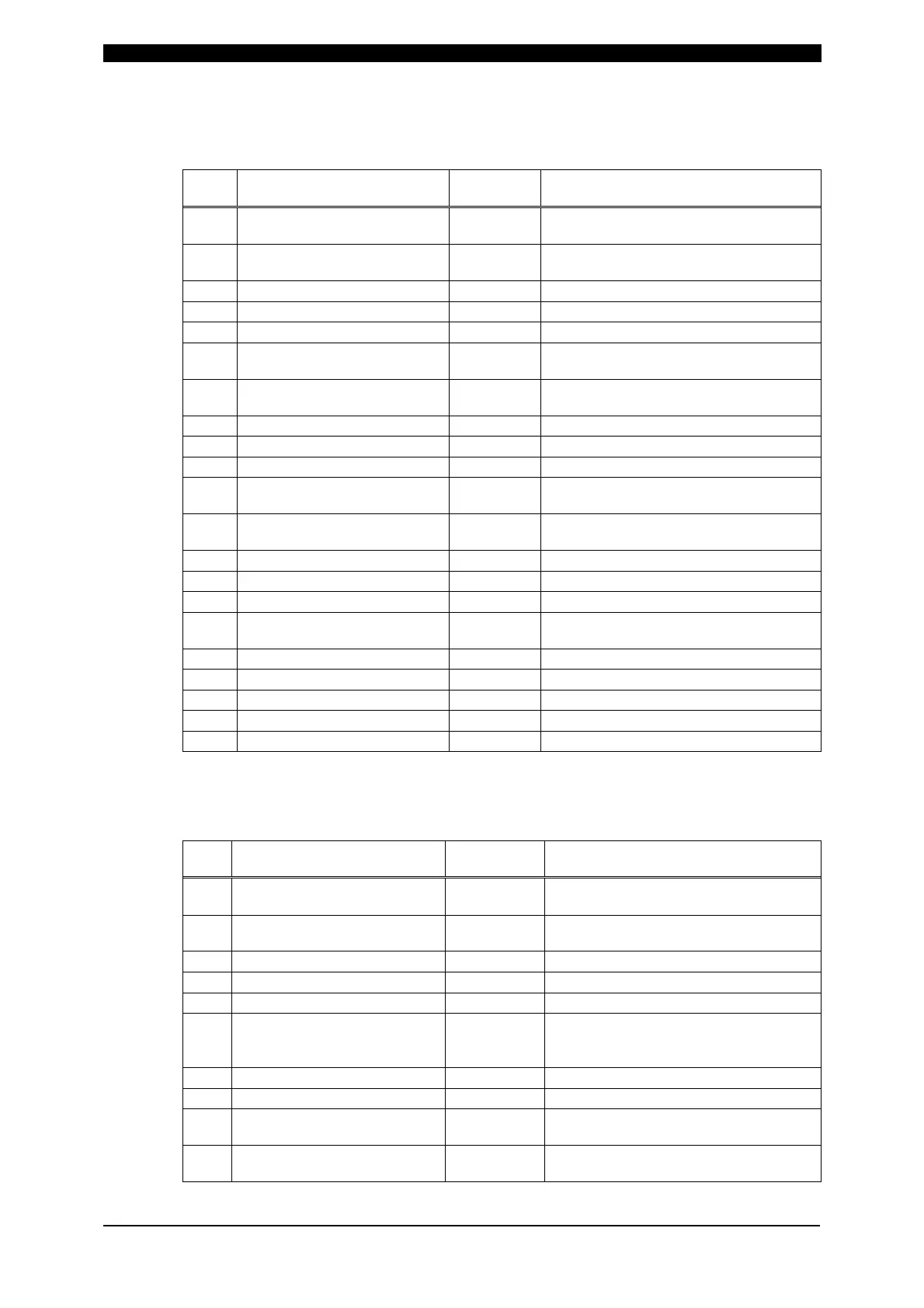
Screen 04 (MONITOR data) (Data reading only)
Specific data in accordance with Schedule No. (Schedule No.: 001 to 255)
Item Contents
Character
String
Range
1 Unit of time n,
m: ms
C: CYC
2 Monitor time of WELD1 nnn,
000 to 999 (ms mode)
000 to 050 (CYC mode)
3 Monitor current of WELD1 n.nn, 0.00 to 9.99 (kA)
4 Monitor voltage of WELD1 n.nn, 0.00 to 9.99 (V)
5 Monitor power of WELD1 nn.nn, 00.00 to 99.99 (kW)
6
Monitor pulse width of
WELD1
nn.n, 00.0 to 99.9 (%)
7 Monitor time of WELD2 nnn,
000 to 999 (ms mode)
000 to 050 (CYC mode)
8 Monitor current of WELD2 n.nn, 0.00 to 9.99 (kA)
9 Monitor voltage of WELD2 n.nn, 0.00 to 9.99 (V)
10 Monitor power of WELD2 nn.nn, 00.00 to 99.99 (kW)
11
Monitor pulse width of
WELD2
nn.n, 00.0 to 99.9 (%)
12 Monitor time of WELD3 nnn,
000 to 999 (ms mode)
000 to 050 (CYC mode)
13 Monitor current of WELD3 n.nn, 0.00 to 9.99 (kA)
14 Monitor voltage of WELD3 n.nn, 0.00 to 9.99 (V)
15 Monitor power of WELD3 nn.nn, 00.00 to 99.99 (kW)
16
Monitor pulse width of
WELD3
nn.n, 00.0 to 99.9 (%)
17 Step No. of VALVE1 n, 1 to 9
18 STEP COUNT of VALVE1 nnnn, 0000 to 9999
19 Step No. of VALVE2 n, 1 to 9
20 STEP COUNT of VALVE2 nnnn, 0000 to 9999
21 WELD COUNT nnnn 0000 to 9999
Screen 05 (SYSTEM data)
Common data (Schedule No.: 000)
Item Contents
Character
String
Range
1*
WELDTRANS
FREQUENCY
nnnn, Transformer frequency (Hz)
2*
POWER SOURCE
FREQUENCY
nn, 50 or 60 (Hz)
3* Model name nnnnnnnn,
IS-200A
␣
4* ROM VERSION Vnn-nnn, V00-00A ~
5 DELAY START SET nn, 01 to 20 (ms)
6 START SIGNAL MODE n,
0: LATCHED
1: PULSED
2: MAINTAINED
7 END SIGNAL TIME nnn, 010 to 200 (ms)
8 END SIGNAL MODE n, 0, 1, 2
9 PARITY CHECK n,
0: OFF
1: ON
10 STEPPER MODE n,
0: OFF
1: ON