Testing Procedures
TT
TT
T
o ao a
o ao a
o a
vv
vv
v
oid the risk of electric shocoid the risk of electric shoc
oid the risk of electric shocoid the risk of electric shoc
oid the risk of electric shoc
k,k,
k,k,
k,
per per
per per
per
sonal injursonal injur
sonal injursonal injur
sonal injur
y ory or
y ory or
y or
death, disconnect power before servicing, unless testingdeath, disconnect power before servicing, unless testing
death, disconnect power before servicing, unless testingdeath, disconnect power before servicing, unless testing
death, disconnect power before servicing, unless testing
requires it.requires it.
requires it.requires it.
requires it.
WARNING
37 RS2310002 Rev. 1
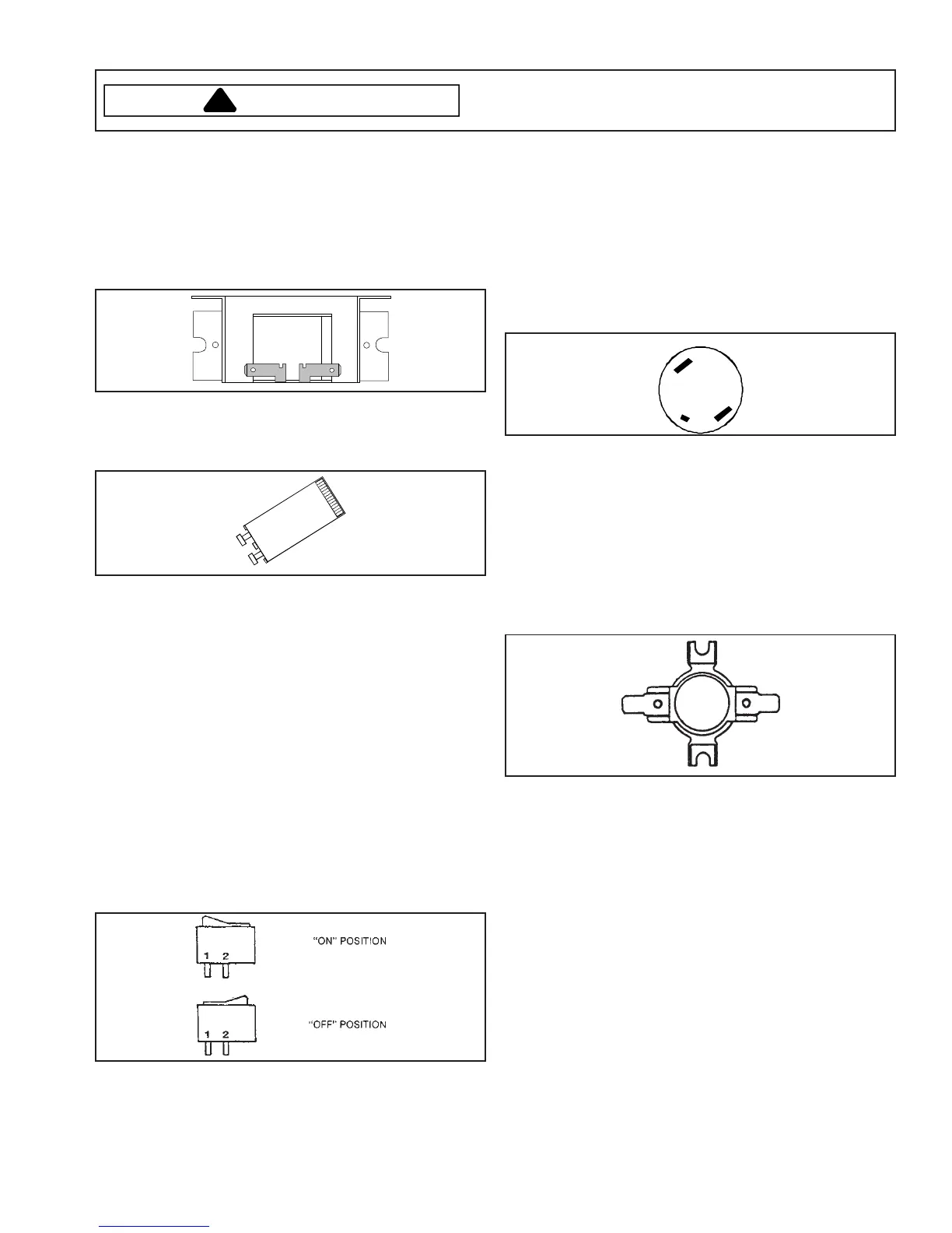
Fluorescent Light Ballast
1. Turn off power to the range.
2. Remove wires connected to ballast, and measure
from terminal to terminal.
• If infinite or zero resistance is indicated replace
ballast.
• Resistance should be indicated, but not a direct
short.
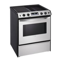
Fluorescent Light Starter
If light does not illuminate verify voltage to ballast. If
voltage is present, and ballast check OK, replace starter.
Fluorescent Light
If fluorescent tube has blackened ends and light
flicker's, verify proper connection of tube, or replace
tube.
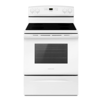
Oven Light Switch
The oven light switch is a single pole, single throw
rocker type switch mounted in the control panel. Follow
the procedures below to test the switch.
1. Turn off power to the range.
2. Disconnect the switch wire leads.
3. Attach an ohmmeter, set to the R x 1 scale, to the
switch terminals 1 and 2. When the switch is set to
the ON position, continuity should be indicated and
open contacts should be indicated when the switch
is set to the OFF position.
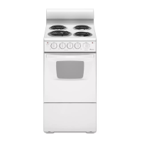
Oven Door Switch
Clean Safety/Light Switch (Power Off)
1. The switch has NO (normally open), NC (normally
closed), and C (common) contacts.
2. Check the switch with an ohmmeter between C and
NC with the plunger out. Continuity should exist.
With the plunger in, no continuity.
3. Check the switch with an ohmmeter between C and
NO with the plunger in. Continuity should exist. With
the plunger out, no continuity.
C
NO
NC
NOTE: When facing the range, the switch is on the left.
Oven High Limit/Fan Switch
Located on the rear of unit and connecting to the L2 side
of electric supply, this switch is normally closed but will
open if external temperature exceeds limits listed below.
Part Number Open Close
308417 115°F 155°F
316971 240°F 210°F
1. Turn off power to range.
2. Remove lower rear access panel on back of range.
3. Disconnect wires from switch terminal connections.
4. Attach ohmmeter leads to switch terminals. At
ambient room temperature (70°F.) continuity should
be indicated.